


Using the Status Registers
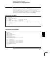
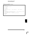
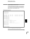
The following example shows how you can use the multimeter’s status
registers to determine when a command sequence is completed. For
more information, see “The SCPI Status Model,” starting on page 134.
The example is shown in BASIC and QuickBASIC (see page 190).
10 REAL Aver,Min_rdg,Max_rdg
20 INTEGER Val,Hpib,Mask,Task
30 ASSIGN @Dmm TO 722
40 CLEAR 7 ! Clear GPIB and dmm
50 OUTPUT @Dmm; "*RST" ! Reset dmm
60 OUTPUT @Dmm; "*CLS" ! Clear dmm status registers
70 OUTPUT @Dmm; "*ESE 1" ! Enable "operation complete" bit to set
! "standard event" bit in status byte
80 OUTPUT @Dmm; "*SRE 32" ! Enable "standard event" bit in status byte
! to pull the IEEE-488 SRQ line
90 OUTPUT @Dmm; "*OPC?" ! Assure synchronization
100 ENTER @Dmm; Val
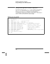
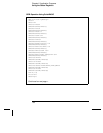
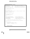
110 !
120 ! Configure the multimeter to make measurements
130 !
140 OUTPUT @Dmm; "CONF:VOLT:DC 10" ! Set dmm to 10 volt dc range
150 OUTPUT @Dmm; "VOLT:DC:NPLC 10" ! Set the integration time to 10 PLCs
160 OUTPUT @Dmm; "TRIG:COUN 100" ! Dmm will accept 100 triggers
170 OUTPUT @Dmm; "CALC:FUNC AVER;STAT ON" ! Select min-max and enable math
180 OUTPUT @Dmm; "INIT" ! Place dmm in "wait-for-trigger" state
190 OUTPUT @Dmm; "*OPC" ! Set "operation complete" bit in standard event
! registers when measurement is complete
200 !
210 Hpib=7
220 ON INTR Hpib GOSUB Read_data
230 Mask=2 ! Bit 1 is SRQ
240 ENABLE INTR Hpib;Mask ! Enable SRQ to interrupt the program
250 !
260 ! Execute other tasks while waiting for data
270 !
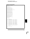
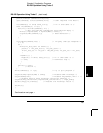
GPIB Operation Using BASIC
Continued on next page >
Chapter 6 Application Programs
Using the Status Registers
188