


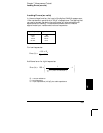
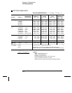
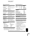
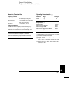

DC Characteristics
Function
DCV, DCI, and
Resistance
Digits
6
1
⁄
2
6
1
⁄
2
5
1
⁄
2
5
1
⁄
2
4
1
⁄
2
Readings/s
0.6 (0.5)
6 (5)
60 (50)
300
1000
Additional
Noise Error
0% of range
0% of range
0.001% of range
0.001% of range
0.01% of range
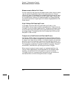
System Speeds
[ 9 ]
Function Change
Range Change
Autorange Time
ASCII readings to RS-232
ASCII readings to GPIB
Max. Internal Trigger Rate
Max. External Trigger Rate to Memory
Max. External Trigger Rate to GPIB
26/sec
50/sec
<30 ms
55/sec
1000/sec
1000/sec
1000/sec
900/sec
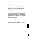
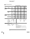
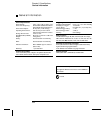
Operating Characteristics [ 8 ]
[10]
[10]
Measurement Noise Rejection
60 Hz ( 50 Hz ) [ 5 ]
DC CMRR
Integration Time
100 PLC / 1.67s (2s)
10 PLC / 167 ms (200 ms)
1 PLC / 16.7 ms (20 ms)
0.2 PLC / 3 ms (3 ms)
0.02 PLC / 400
µs (400 µs)
140 dB
Normal Mode Rejection
[ 6 ]
60 dB [ 7 ]
60 dB [ 7 ]
60 dB [ 7 ]
0 dB
0 dB
[12] Accuracy specifications are for the voltage measured at
the input terminals only. 1 mA test current is typical. Variation
in the current source will create some variation in the voltage
drop across a diode junction.
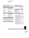
DC Voltage
Measurement Method:
A/D Linearity:
Input Resistance:
0.1 V, 1 V, 10 V ranges
100 V, 1000 V ranges
Input Bias Current:
Input Terminals:
Input Protection:
Resistance
Measurement Method:
Max. Lead Resistance:
(4-wire ohms)
Input Protection:
DC Current
Shunt Resistor:
Input Protection:
Continuity / Diode Test
Response Time:
Continuity Threshold:
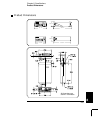
DC:DC Ratio
Measurement Method:
Input HI-LO
Reference HI-Input LO
Input to Reference
Continuously integrating, multi-slope III
A/D converter.
0.0002% of reading + 0.0001% of range
Selectable 10 M
Ω or >10 GΩ [11]
10 MΩ ±1%
< 30 pA at 25°C
Copper alloy
1000 V on all ranges
Selectable 4-wire or 2-wire ohms.
Current source referenced to LO input.
10% of range per lead for 100
Ω, 1 kΩ
ranges. 1 k
Ω per lead on all other ranges.
1000 V on all ranges
0.1
Ω for 1A, 3A. 5Ω for 10 mA, 100 mA
Externally accessible 3A, 250 V fuse
Internal 7A, 250 V fuse
300 samples/sec with audible tone
Adjustable from 1
Ω to 1000 Ω
Input HI-LO / Reference HI-LO
100 mV to 1000 V ranges
100 mV to 10 V ranges (autoranged)
Reference LO to Input LO voltage < 2 V
Reference HI to Input LO voltage < 12V
Measuring Characteristics
Teflon is a registered trademark of E.I. duPont deNemours and Co.
Autozero OFF Operation
Following instrument warm-up at calibration temperature ±1°C
and <10 minutes, add 0.0002% range additional error + 5 µV.
Settling Considerations
Reading settling times are affected by source impedance,
cable dielectric characteristics, and input signal changes.
Measurement Considerations
Agilent recommends the use of Teflon
â
or other high-impedance,
low-dielectric absorption wire insulation for these measurements.
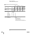
[ 1 ] Specifications are for 1-hour warm-up at 6
1
⁄
2
digits.
[ 2 ] Relative to calibration standards.
[ 3 ] 20% overrange on all ranges, except 1000 Vdc, 3 A range.
[ 4 ] Specifications are for 4-wire ohms function, or 2-wire
ohms using Math Null. Without Math Null, add 0.2
Ω
additional error in 2-wire ohms function.
[ 5 ] For 1 kΩ unbalance in LO lead.
[ 6 ] For power-line frequency ± 0.1%.
[ 7 ] For power-line frequency ± 1%, subtract 20 dB.
For
± 3%, subtract 30 dB.
[ 8 ] Readings speeds for 60 Hz and ( 50 Hz ) operation,
Autozero Off.
[ 9 ] Speeds are for 4
1
⁄
2
digits, Delay 0, Autozero OFF,
and Display OFF. Includes measurement and data
transfer over GPIB.
[ 10 ] Add 20 µV for dc volts, 4 µA for dc current, or
20 m
Ω for resistance.
[ 11 ] For these ranges, inputs beyond ±17V are
clamped through 100 k
Ω (typical).
8
Chapter 8 Specifications
217