


Avanti
Security control panels
8 fully programmable Zones + PA
and Tamper
External lighting facility to control up
to 2000 watts of external security
lighting
3 part set programs
Service timer (selectable)
Chime on any Zone
Entry/Exit timers programmable in
one second increments (0-99 secs)
6 Communicator outputs (RS panels)
7 codes Engineer-Manager-Holiday-4
User codes (individual duress on RS)
Up to 4 remote keypads
K-600HW
engineer manual
Introduction
Avanti is a flexible range of fully featured security control
panels suitable for domestic and light commercial
applications designed to meet the installation
requirements of EN50131-1-6.
Avanti is supplied with on-board keypad or remote end
station; either option allows you to fit up to 4 additional
backlit RKP’s.
With 8 fully programmable zones plus PA and tamper,
doorbell, quick set, fire and the ability to control security
lighting via a Drive Module the Avanti provides you with
a cost-effective solution for most applications.
RS versions provide 6 digital ports for use with a wire on
communicator.
EMC:
Emissions EN50081-1: 1992
Immunity EN50130-4: 1995
Low Voltage Directive (LVD) 73/23/EEC
1 Installation
1.1 System Design
Before commencing installation it is important to
familiarise yourself with these instructions.
Care should be taken when planning the system that the
control panel is sited close to a convenient mains supply
and is not visible from the outside of the property.
If you are using the Avanti ES then the end station may
be located in a cupboard in the hall or under the stairs.
The remote keypads should be located so that the user
can access them easily during entry and exit.
1.2 Fixing
First disconnect the AC and internal speaker wiring,
releasing the PCB from the case.
Offer the case to the wall, mark, drill and plug for three
hole fixing using a suitable bit.
Where required remove trunking cut outs and drill wall for
cable entry.
Screw in top fixing (No8 x 2
1
2
”screw) and leave protruding
1
2
”, mount the box utilising the keyhole, align and secure
using 2 off No8 x 2
1
2
”
screws.
Refit the PCB and reconnect the speaker and AC wires.
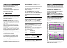
1.3 Pre-installation test
Observing the correct polarity, Connect the battery to the
terminals marked Batt + -
The panel will now go into alarm condition. Entering the
user code (0123) will silence the system. The Tamper
and Power LED’s will be lit with Day & Zone flashing.
To reset the panel re-enter the user code and the Day &
Power LED’s will become steady (DAY mode).
Upon completion of initial test, disconnect the battery.
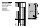
1.4 Wiring
Wire each of the zones in turn making sure to connect
tampers in series then continue to wire PA, internal and
external sounder and strobe and any additional remote
keypads. Finally on RS models connect any
communicating devices.
1.5 RKPs
Up to 4 RKP’s may be wired in parallel with the tamper
being wired in series using a single 6-core cable to a
maximum of 100 metres.
1.6 Utility Outputs
A unique feature of the Avanti is the ability to operate
security lighting. To utilise this value-added feature a
Lighting Drive Module (LDM) is required (available
separately).
To install floodlights the LDM is wired into the RKP
terminals and lighting is operated through Channels A &
B. Depressing the A or B keys on the control panel will
switch up to 1000 watts per channel (total available 2000
watts).
If you choose to install a PIR then this can be wired into
any unused zone which when activated will switch the
lighting on for a period of 15 seconds.
1.7 Mains Connection
This equipment should be installed by a suitably
qualified electrician and must be wired with cable
rated at least 1 Amp, 230 volts AC. Ensure that a
suitable disconnect device such as a fused spur or
removable fuse is fitted to the mains supply.
™