


4.9 Test Menu.
The Test Menu is entered from the Engineers menu by
pressing Key 9. The alarm panel has several test modes
making life a little easier for the installation engineer.
They are as follows:
• Press 1 to switch bell drive on.
• Press 2 to switch strobe drive on.
• Press 3 to switch all speakers on.
• Press 0 to switch all outputs off.
• Press 6 to enter walk test.
• Press 9 to show zone status.
• Press Z To Exit the Walk Test menu.
On entering the Test menu, All the zone LED’s will be
switched off, and the PA and Tamper LED’s will be
flashing, indicating a test must be selected.
WALK TEST.
On entering the zone walk test, all of the zones will be
reset, and all zone LED’s will be switched off. The PA and
Tamper LED’s will be flashing indicating that the engineer
is within the walk test function.
Each time a zone is activated or de-activated the internal
sounders will bleep. When a zone becomes active, the
zone LED’s for all active zones will be lit.
Press Z To exit walk test. This will move you back to the
test menu, the PA and Tamper LED’s will flash. To return
to Engineer Menu Press Key Z.
4.10 Setting Up the System Flags.
Set up System Flags menu is entered from the Engineers
menu, by pressing KEY 0.
There are 3 system flags that can be set to tailor the way
that the system operates.
On entering the set-up system flags menu, zones 2 and 3
LED’s will be lit according to the zone attributes that are
selected. The flags are as follows:
LED 2 On for Bell follow.
LED 3 On for Key switch operation (PTS input).
LED 3 Off for Push to set (PTS input).
Pressing the Key number that represents the LED number
will toggle that attribute.
Press A To Accept / Press B To Abort the changes.
4.11 Viewing the Event Log.
The Event Log menu is entered from the engineers menu,
by pressing
key.
The Day LED will be extinguished to indicate Event Log
mode.
The Zone, PA and Tamper LED’s will now show the latest
event. Whichever Zone, PA or Tamper LED is flashing is
the first activated, and whichever Zone, PA or Tamper is
lit was triggered after the first event, but before the
system was un-set.
To navigate through the event log, the following keys are
used:
Press 1 To Jump to the oldest event.
Press 2 To move to 1 event older.
Press 3 To move to 1 event newer.
Press 4 To Jump to the newest event.
Press 9 To Reset the event log.
Press Z To Return to Engineer Menu.
If there are less than 16 events, then it is only possible to
scroll between the number of events within the event log.
4.12 Changing Chime in Day Mode
Chime is a low security attribute that can be programmed
onto any zones. In Day mode, the Chime Attribute for
each of the 8 zones may be changed in the following
manner:
Press
All of the zones that will chime when they are activated
will have the LED for that zone lit up.
Press the key that represents the zone that the zone
attribute requires changing for. This will toggle the LED
for that zone. When the LED is lit, that zone will chime
when it is activated.
Once the changes have been made then:
Press A To Accept / Press B To Abort the changes.
5 Remote signalling
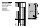
Communicator Terminals
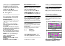
The RS variant of the control panel is fitted with
communicator outputs on the top left side of the PCB.
13V output
This output, along with the 0V output provides power for
a wire on communicator, which is fused at 0.5A.
Note: Care should be taken to ensure that the maximum
load on the power supply is less than 350ma for auxiliary
devices such as communicators, passives but excludes the
Bell/Strobe outputs.
Line Fail
This input allows the communicator to inform the panel
that there is a line fault.
When the panel is in DAY mode a line fail will cause the
Tamper LED to flash but will not cause an alarm.
A line fault when the panel is SET will not cause an alarm,
but will cancel any bell delay programmed into the panel.
Outputs
There are 6 outputs labelled FIRE, PA, INT, SET,
ABORT, and CONF. Each output sits at 12V when not
active and is pulled to approximately 0.8V when active.
Each output can sink 50ma, giving enough energy to drive
a relay if required. These outputs would normally be
connected to a STU or communicator.
FIRE – This output becomes active (0V) when the panel
is activated by a fire input.
PA – This output becomes active (0V) when the panel is
triggered by:
1) PA input becoming active
2) Duress code being entered
INT – This intruder output becomes active (0V) when the
panel is triggered whilst the panel is SET.
SET – This output becomes active (0V) when the panel is
SET.
ABORT – This output becomes active (0V) when an alarm
condition is reset.
CONF – This confirmed output becomes active (0V) when
2 or more zones are triggered when the panel is SET.
Note: If the communicator or STU is being powered by a
separate power supply, the 0V of the external power
supply must be connected to the 0V of the alarm panel.