


724-746-5500 | blackbox.com
Chapter 3: Operation
Page 15
3.3 Quick Test
A
B
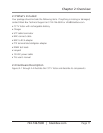
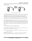
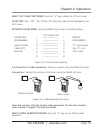
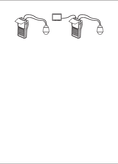
Figure 3-2. Quick test setup.
A. Viewing a camera image: Follow diagram A to connect a CCTV camera (includ-
ing PTZ control) to the tester. The camera’s video output connects to the tester’s
VIDEO IN BNC connector. The camera’s PTZ control wires connect to tester’s
RS-485/422 control block (using the terminal block/alligator clip adapter provided
with the tester). Turn ON the tester and select menu item “2.” The camera’s video
will display on the tester screen. More detailed instructions follow in this manual.
B. Connecting a monitor: Follow diagram B to connect a CCTV monitor to the
tester. The tester’s VIDEO OUT BNC connects to the monitor’s video input connector.
You can drive the monitor with the video signal generated by the tester (menu item
#4, then TELE) or in “looped mode” with a camera’s video connected to the tester’s
VIDEO IN BNC (menu item #4, then WIDE). More detailed instructions follow in this
manual.
3.4 Main Menu (in order of appearance)
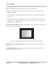
3.4.1 Selection 1: System Setup: Display battery status, set auto-off time, and set
up PTZ parameters to match your CCTV camera.
NOTE: If you are not using the PTZ (pan/tilt/zoom) test feature, there is no need to
set the PTZ parameters.
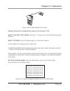
ENTERING AND EXITING: Press “1” to enter the setup screen. Press “MENU” to
return to the Main Menu. A typical configuration is as shown in Figure 3-3.