


www.bowens.co.uk
Fitting the Modelling Lamp
6
The flash power output is variable over five f-stops from full to 1/32 power. The maximum power available
depends upon the model (See specification table) and is denoted by the number 6 on the control panel.
The power settings are denoted in steps of 1/3 stop. The numeric divisions indicate full one stop
divisions.
When switched 'ON' from either a mains or battery supply, the unit will charge. Once the unit has charged
to the desired power level, the Green READY lamp will illuminate indicating that the unit is ready to fire.
Note: If the unit is subjected to rapid operation over extended periods, it may automatically go into an
overheat condition. In this condition, the Green READY lamp will illuminate to indicate the presence of
power, while the charging and modelling functions are disabled in order to allow the unit to cool. The unit
will automatically resume operation once cooled sufficiently.
HINT - In an overheat condition, the unit will typically take 15 minutes to cool down.
By switching OFF and then ON again after say 5 minutes, the unit can be re-activated in order to get a
few extra shots if needed.
Synchronisation
There are several ways to trigger the Esprit Gemini
Open Flash:
For testing or multiple flash applications the Open Flash Pushbutton can be used.
Sync Socket:
The standard quarter inch jack type socket on the rear panel of the unit may be used for direct connection
to a camera set to 'x' synchronisation. Two Esprit units may be connected together using a 'y' connector.
An Infra Red Receiver or Omnicell may also be plugged into this socket. The socket operates at +5V
and is safe for use on digital cameras.
Photocell:
The Esprit Gemini has a built in switchable photocell enabling the unit to be triggered by the flash from
any other flash unit or a small camera mounted flash gun. The photocell is mounted behind the red
transparent cover on the top of the unit. The photocell on/off switch is located on the rear control panel.
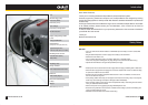
Flash Power Control
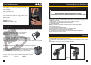
Switch off and disconnect from the supply. Screw modelling lamp into ES lampholder in the centre of the
reflector. Allow lamp to cool before removing.
Note: It is recommended that a Photoflood or Halostar bulb with a maximum wattage of 275W is used.
The manufacturer will not accept liability on the use of any lamp with a greater wattage than 275W.
www.bowens.co.uk
Modelling Lamp Control
7
With the modelling lamp control switch (Fig.1. 3) in the upper position the modelling light is OFF. With
the modelling light set to centre the modelling light will go out when the unit is flashed and come back
on when the unit comes to ready. This enables the photographer to see from the camera position that
all Esprit units in use have fired. With the switch set in the lower position the modelling lamp stays on
all the time. The modelling light may be varied in ratio with the flash power output by aligning the
modelling Knob with that of the flash control (see page 4).
Fuse
The modelling and flash circuitry is protected by a single 20mm fuse mounted on the rear panel. Never
replace the fuse with one of a different rating. As the fuse may blow when the modelling lamp fails always
check the fuse when replacing the bulb. A spare fuse is supplied in the fuse holder. Always switch OFF
and disconnect the Esprit Gemini unit from the power supply before changing the bulb or fuse.
Audible Ready Beep
Set the Sounder Switch to 'ON' to give a short beep when the unit comes to ready, to provide an audible
'Ready' confirmation. The sounder switch is located on the rear control panel (page 4).
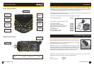
Fitting / Removing Reflectors
A range of reflectors is available for the Esprit Gemini unit. To fit, slide the neck of the reflector over the
front of the unit. Align the three pegs on the reflector with the three slots in the retaining ring. Press down
and turn clockwise to lock.
To remove reflector, pull back Latch Knob (page 4), turn the reflector fully anti-clockwise and withdraw.
If an umbrella is to be used a 'Wide Angle Reflector' should be fitted and the umbrella fitted through the
mounting hole in the mounting bracket and locked in position with the knurled screw.
Note: Take care when fitting / removing reflectors not to damage the flashtube assembly. The flashtube
is very delicate, avoid unnecessary handling of the glass tube. Always switch off and disconnect from the
mains supply before fitting and changing reflectors.
Warning High Voltage!
Do not touch the flashtube assembly for thirty minutes after disconnecting from
supply.