


Copyright © 2005 Linear LLC 9900626 A
7440
Color CCTV Camera
Installation Instructions
PRODUCT DESCRIPTION
The Model 7440 Color CCTV Camera provides signifi cant performance in a small
package. The camera’s high-resolution, low lux 1/3” CCD element provides clear
images even in low light conditions. The built-in automatic iris control ensures an
optimal picture on bright, sunny days without “blooming” or “washouts”. The fi xed
focal-length lens has a horizontal viewing angle of 120° with no “fi sh eye” distortion.
The camera is housed in a miniature, weather-tight, die-cast aluminum enclosure that
is built to withstand the harshest weather conditions. The adjustable mounting bracket
allows the camera to be rotated 360° and pivot 90° to enable viewing in virtually
any position. A locking screw on the mounting bracket secures the camera after the
viewing angle is adjusted. The mounting bracket attaches to the mounting surface
with the three screws provided.
FEATURES
• Extremely small size make the camera easy to conceal
• Auto white balance enables true color reproduction in varying light conditions
• Ideal for a wide variety of applications including residences, nurseries, storefronts,
swimming pool areas, boat docks, cabanas, etc.
• Outstanding video signal-to-noise ratio of 48 dB for a noise-free picture
• Low power requirements ensure low heat and long life
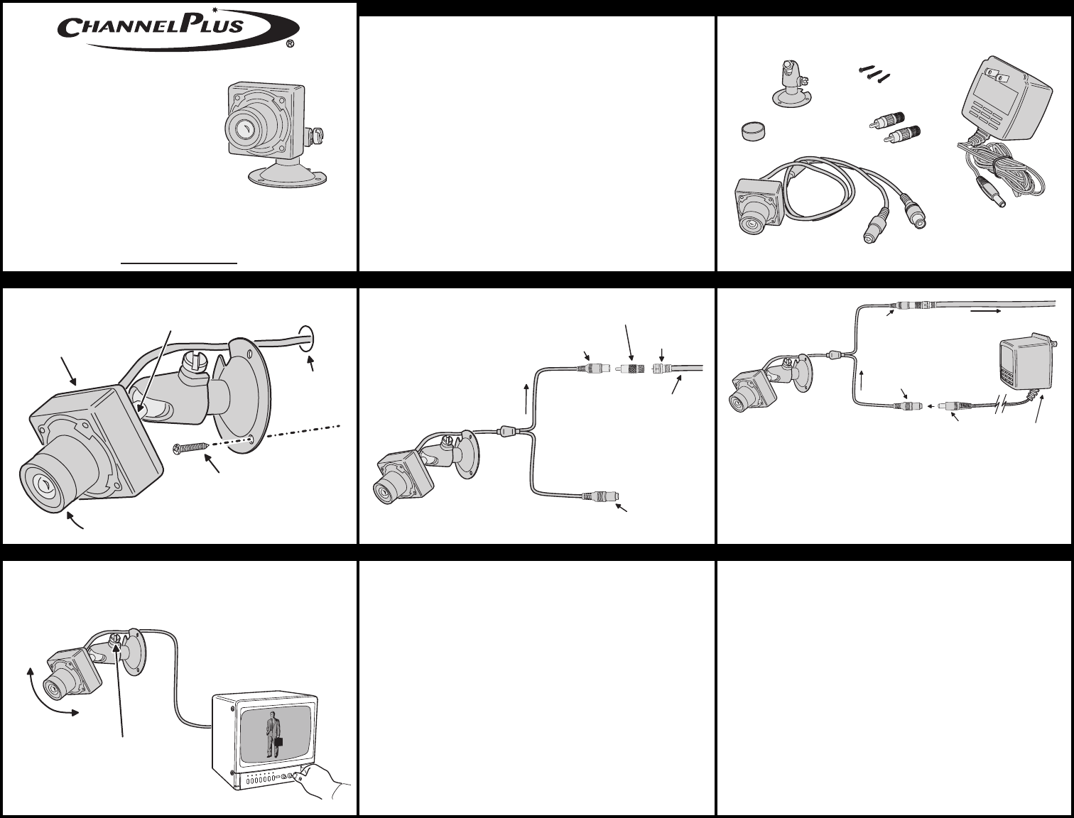
CAMERA COMPONENTS
CAMERA MOUNTING VIDEO CONNECTION POWER CONNECTION
ALIGNMENT & TESTING SPECIFICATIONS
IMAGING ELEMENT: CCD
LENS: 2.1 mm, f 2.0
LUX: 0.5 minimum
RESOLUTION: 380 TV Lines
HORIZONTAL VIEWING ANGLE: 120°
VERTICAL VIEWING ANGLE: 100°
VIDEO OUTPUT: 1 volt peak-to-peak
VIDEO OUTPUT IMPEDANCE: 75Ω
POWER REQUIREMENTS: 12 VDC @ 90 mA
(power supply included)
WIRING REQUIREMENTS: VIDEO: RG-59 or RG-6
(RG-6U recommended)
POWER: 18 AWG 2-conductor
LIMITED WARRANTY
Linear LLC warrants this product to be free from defects in material and workmanship for 1 year. The time period
will be measured using the date code labeled on the product. Linear LLC is not responsible for damage to the
product resulting from the buyer’s improper handling, stocking or warehousing of the product. Any implied warranty
arising from the sale of the product including implied warranties of merchantability and fitness for purpose are
limited. Linear LLC shall not be responsible for any losses, damages or expenses, whether direct, consequential,
or incidental arising from the use or the inability to use the product. Some states and countries do not allow
limitations or how long an implied warranty lasts or the exclusion or limitation or incidental or consequential
damages, so the above exclusions may not apply. The Linear LLC warranty gives specific legal rights in addition
to other rights, which may exist and vary from state to state and country to country.
The warranty is limited to repair or replacement of products returned, freight prepaid, to Linear LLC, there is NO
PROVISION FOR LABOR COST OR OTHER REIMBURSEMENTS OF ANY KIND.
1. Failures due to product abuse, such as negligence, improper use, and electrical surge including damage from
lightning, water damage or other damage due to natural disasters are not covered by the warranty. The most
common form of product abuse is surge damage caused by lightning.
2. The warranty shall also be voided by any tampering with the date code, labels or other markings on the
product.
3. Products that are damaged in transit to Linear LLC due to improper packaging or by the carrier (shipping
company) will not be covered under the warranty. If the product was damaged or lost by the carrier, it is the
sender’s responsibility to create a claim against the carrier.
4. The user is responsible for all labor costs associated with removing, reinstalling and returning the product to
Linear LLC.
Linear LLC, at its option, will repair or replace the defective product. Replacements will be made from B-Stock, if
an exact replacement is not available, Linear LLC, at its option, will select the nearest equivalent product. The user
is responsible for freight charges to Linear LLC. Linear LLC will return warranted repaired or replacements by UPS
Ground or an equivalent service. A customer may pay the additional costs for second-day or next-day service.
All products returned for warranty service require a Return Product Authorization Number (RPA#). Contact Linear
Technical Services at 1-800-999-5225 for an RPA# and other important details.
Linear LLC
2055 Corte Del Nogal, Carlsbad, CA 92009, USA
760-438-7000
800-999-5225
fax: 760-931-1340
www.channelplus.com
ADJUSTABLE
STAND
MOUNTING
SCREWS
LENS
CAP
RCA-TO-F
ADAPTERS
12 VDC 500 mA
POWER SUPPLY
TRANSFORMER
COLOR
CAMERA
POWER AND
VIDEO CONNECTORS
ATTACH THE CAMERA TO
STAND (TO KEEP THE PICTURE
RIGHT-SIDE UP, THE WIRE
SHOULD EXIT ABOVE THE
STAND MOUNTING HOLE)
TIGHTEN THE LOCKNUT
AGAINST THE CAMERA
TO SECURE IT TO THE STAND
FOR RECESSED
WIRING DRILL
A 9/16" HOLE
ATTACH THE CAMERA TO THE
MOUNTING SURFACE WITH THE
THREE SCREWS PROVIDED, OR
USE OTHER APPROPRIATE
FASTENERS FOR THE SURFACE
LENS CAP
REMOVED
VIDEO OUT
FROM
CAMERA
BLACK CONNECTOR
POWER INPUT
FEMALE MINI-JACK
MALE RCA
TO FEMALE
TYPE-F ADAPTER
RG-59 OR RG-6 COAX TO VIDEO
MONITOR OR CHANNELPLUS
MODULATOR
USE THE SECOND RCA-TO-F
ADAPTER AT THE OTHER
END OF THE COAX IF REQUIRED
YELLOW CONNECTOR
VIDEO OUTPUT
FEMALE RCA
MALE
F-CONNECTOR
7440 CAMERA
CONNECT THE CAMERA'S VIDEO OUTPUT
TO A MONITOR OR TO A CHANNELPLUS MODULATOR
NOTE: FOR THE BEST PICTURE, RG-59U
OR RG-6U COAX IS RECOMMENDED.
RG-6U IS MILITARY GRADE COAX THAT
HAS A BRAIDED SHIELD AND 20 AWG
SOLID COPPER CENTER CONDUCTOR
MAXIMUM RECOMMENDED
VIDEO CABLE LENGTH:
RG-59 750-1000 FEET
RG-6 1000-1500 FEET
VIDEO OUT
FROM CAMERA
BLACK CONNECTOR
POWER INPUT
FEMALE MINI-JACK
12 VDC 500 mA
POWER SUPPLY
TRANSFORMER
7440 CAMERA
CONNECT THE CAMERA'S
POWER INPUT TO THE
POWER SUPPLY
TRANSFORMER
TRANSFORMER
MALE MINI-JACK
YELLOW CONNECTOR
VIDEO OUTPUT
FEMALE RCA
PLUG THE
TRANSFORMER
INTO A 120 VAC
OUTLET
MAXIMUM RECOMMENDED
POWER WIRE LENGTH:
1500 FEET
IN MOST INSTALLATIONS, THE POWER WIRE BETWEEN
THE TRANSFORMER AND THE CAMERA WILL NEED TO
BE EXTENDED
USE 18 AWG STRANDED UN-SHIELDED 2-CONDUCTOR
WIRE TO ADD TO THE TRANSFORMER'S WIRE LENGTH
(DO NOT CUT THE POWER WIRE ON THE CAMERA)
OBSERVE POLARITY WHEN SPLICING THE WIRE! THE
WHITE STRIPE ON THE TRANSFORMER'S WIRE IS
POSITIVE (+)
ADJUST THE CAMERA
TO VIEW THE DESIRED AREA
TIGHTEN THE LOCKING
SCREW ON THE STAND
AFTER THE CAMERA IS
ADJUSTED
ADJUST THE MONITOR
FOR THE BEST PICTURE