


1-5
Cisco Video Surveillance IP PTZ Dome Camera User Guide, Cisco 2900 Series IP Dome
OL-24281-01
Chapter 1 Installation
Mounting
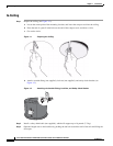
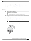
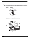
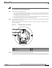
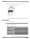
Step 3 Connect the auxiliary, alarm, and other wiring to the back box circuit board (see Figure 1-6).
Note Aux 1: Maximum 2 A at low voltage (<40 V).
Aux 2: Maximum 30 mA at 32 VDC.
If you are installing an environmental back box in a railway application, attach a ground wire
from the circuit board power connector to a structural ground using at least 18-gauge wire.
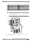
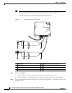
Figure 1-6 Connect the Wiring to the Circuit Board
Step 4 If you plan to use the audio functions, install your audio cables into the audio line-in and line-out
connectors on the TXB-N.
1 RJ-45 Connector 7 Standoff
2 Ethernet Cable 8 UTP Connector
3 Video Coaxial Cable 9 Back Box Circuit Board
4 16-Pin Connector 10 Audio Connectors
5 Heat Sink Standoff 11 TXB-N
6 Captive Screw
VIDEO
UTP+UTP-RX-RX+ TX+TX-PWR- PWR+GND
AUX2
GND
GND
NO
NC
COM
7
6
5
4
3
2
1
ALARMS
AUX1