


1-7
Cisco Video Surveillance IP PTZ Dome Camera User Guide, Cisco 2900 Series IP Dome
OL-24281-01
Chapter 1 Installation
Mounting
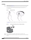
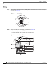
Warning
An electrical short in the back box may occur if the metal BNC connector on the video coaxial cable
is not completely covered by the protective boot.
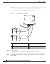
Step 7 Perform one of the following options:
• View video using both analog and IP connections—Connect the video coaxial cable from the back
box circuit board to the coaxial cable coming in from the outside. Make sure that the BNC connector
is completely covered by the protective boot.
• View video using only the IP connection—Make sure that the BNC connector is completely covered
by the protective boot and is out of the way of the back box door.
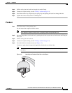
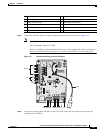
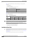
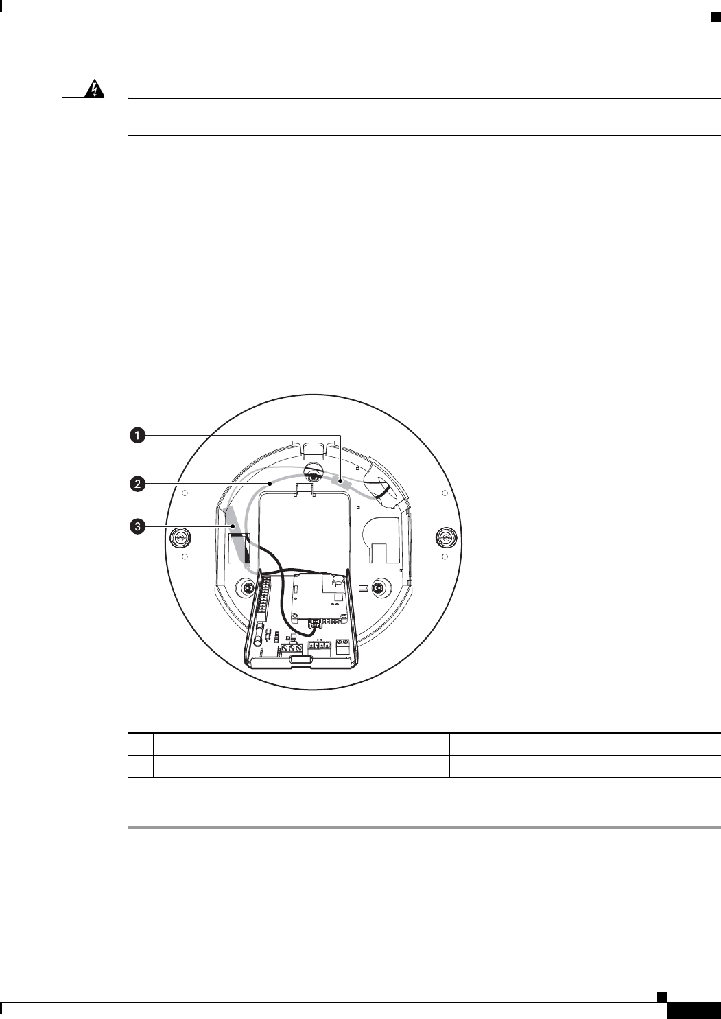
Step 8 Before closing the interconnect door, ensure that no wires are between the top of the heat sink standoff
and the back box (see
Figure 1-8).
Both the video coaxial cable and the Ethernet cable need to be routed carefully to ensure clearance for
the heat sink standoff.
Figure 1-8 Routing the Cables in the Back Box
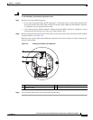
Step 9 Close the interconnect door and snap the tab lock into place.
1 RJ-45 Connector 3 Video Coaxial Cable
2 Ethernet Cable