


1-8
Cisco Video Surveillance IP PTZ Dome Camera User Guide, Cisco 2900 Series IP Dome
OL-24281-01
Chapter 1 Installation
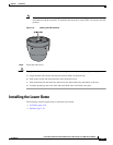
Installing the Dome Drive
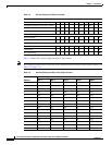
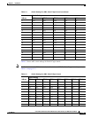
Table 1-1 shows the maximum distances for video coaxial cable types. A cable must meet these
requirements:
• 75-ohm impedance
• All-copper center conductor
• All-copper braided shield with 95 percent braid coverage
Table 1-2 shows the recommended maximum distances for 24 VAC and 24 VDC applications, which are
calculated with a 10 percent voltage drop. (Ten percent is generally the maximum allowable voltage drop
for AC- or DC-powered devices.)
Note Input power for the dome is 24 VAC or 24 VDC. Using 24 VAC input power, power consumption is 23
VA per dome for indoor models and 73 VA for outdoor models. Using 24 VDC input power, power
consumption is 0.7 A (15 W) for indoor models and 3 A (65 W) for outdoor models.
Use a 24 VAC transformer with the following minimum VA:
• 40 VA per dome—For indoor models (without heater)
• 100 VA per dome—For outdoor models (with heater)
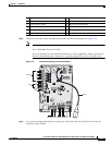
Installing the Dome Drive
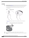
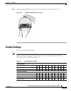
Step 1 If you will view video using both analog and IP connections, set the DIP switches on the top of the dome
drive (see
Figure 1-9).
For DIP switch settings, see the labels located on the top of the dome drive, or see the “Switch Settings”
section on page 1-11.
If you will view video using the IP connection, you do not need to set the DIP switches.
Ta ble 1-1 Video Coaxial Cable Requirements
Cable Type Maximum Distance
RG59/U 750 ft (229 m)
RG6/U 1,000 ft (305 m)
RG11/U 1,500 ft (457 m)
Ta ble 1-2 24 VAC/24 VDC Wiring Distances
AC/DC
Total VA/
Total Watts
Wire Gauge
20 AWG (0.5 mm
2
) 18 AWG (1.05 mm
2
) 16 AWG (1.5 mm
2
) 14 AWG (2.5 mm
2
)
23VA/15 W 123 ft (38 m) 196 ft (60 m) 311 ft (95 m) 495 ft (151 m)
73 VA/65 W 39 ft (12 m) 62 ft (19 m) 98 ft (30 m) 156 ft (48 m)