


2-3
Cisco Video Surveillance 4300 and 4500 High-Definition IP Cameras User Guide
OL-19609-04
Chapter 2 Getting Started
Installing the IP Camera
Step 3
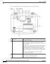
Optional. Use the audio Y cable that is provided with
the IP camera to connect a speaker, microphone, or both
devices to the audio port on the rear of the IP camera.
The audio cable that is provided with the IP includes two
plugs. The cable from an external speaker connects to the
Audio Out plug on the audio cable. The cable from an
external microphone connects to the Audio In plug on the
audio cable.
A speaker plays audio that is captured by a microphone
that is attached to the PC on which you view video from
the camera.
Place the external microphone in a location that allows it
to capture the audio that you want.
Note By default, the IP camera does not transmit or
receive audio. To enable and configure audio, see
the “Streaming Settings Window” procedure on
page 3-3.
Step 4
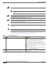
Optional. Use the GPIO ports on the rear of the IP
camera to connect external devices that trigger alarms
(connect through input ports) or respond to alarms
(connect through output ports).
You can connect up to two input devices and two output
devices to these ports:
DI1—Alarm input 1
DI2—Alarm input 2
DO1—Alarm output 1
DO2—Alarm output 2
GND—Ground (for use if needed)
Step 5
Optional. Use the RS-232 ports on the rear of the IP
camera to connect a control device (motorized housing)
that supports the Pelco D protocol.
A RS-232 cable fits into the ports in one way. Make sure
to insert it properly.
Step 6
Connect an STP (shielded twisted pair) Category 5 or
higher network cable to the LAN port on the back of the
camera and to a 100BaseT hub, router, or switch.
If your network provides PoE, the IP camera powers on.
Skip to Step 8.
Table 2-1 Installing the IP Camera (continued)
Action Explanation