


3-9
Cisco Video Surveillance 4300 and 4500 High-Definition IP Cameras User Guide
OL-19609-04
Chapter 3 Configuring and Managing the IP Camera
Feature Setup Windows
If you change the option in this window, you must click the Save Settings button to save the change. If
you do not click this button, changes are not retained when you exit the window. Save Settings appears
at the bottom of the window. You may need to scroll down to it.
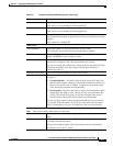
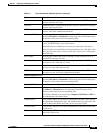
Table 3-5 describes the option in the IO Ports Settings window.
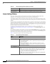
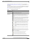
Pan Tilt Settings Window
The Pan Tilt Settings window provides options for configuring pan and tilt functions for the IP camera.
These functions require that the IP camera be installed with a pan/tilt mount that supports the Pelco D
protocol.
If you use a pan/tilt mount that requires RS-422 or RS-485 connections, you must connect the mount to
the IP camera through a Cisco data converter (part number CIVS-KYBD22232-B).
To display the Pan Tilt Settings window, access the configuration windows as described in the
“Performing the Initial Setup of the IP Camera” section on page 2-5, click Feature Setup, then click
Pan/Tilt.
If you change any options in this window, you must click the Save Settings button to save the change.
If you do not click this button, changes are not retained when you exit the window. Save Settings appears
at the bottom of the window. You may need to scroll down to it.
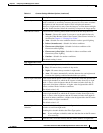
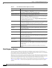
Table 3-6 describes the option in the Pan Tilt Settings window.
Table 3-5 IO Ports Settings Window Options
Option Description
Input Ports Area
Port # Display only. Indicates input port 1 and input port 2.
Current State Display only. Indicates the current state (high or low) of the corresponding
port.
Event Trigger Choose the state (Rising or Falling) that triggers designated camera actions.
When an input port changes to the configured state, the camera determines
that an event has occurred and takes the actions that you have configured.
Output Ports
Port # Display only. Indicates output port 1 and output port 2.
Current State Display only. Indicates the current state (high or low) of the corresponding
port.
Default State Choose the state (low or high) that the corresponding port is set to when the
IP camera powers on or resets.
The port changes to this state when you click Save Settings.
The default setting is High.
Event Action Display only. Indicates the current state (high or low) that the output port
changes to when an event occurs.
Automatic Reset Check this check box if you want the corresponding output port to go back
to its default state after an event occurs.
Duration If you checked the Automatic Reset check box, enter the amount of time, in
milliseconds, that elapses before the port goes back to its default state after
an event changes it from the default state.