


3-9
Cisco Video Surveillance 4300E and 4500E High-Definition IP Camera User Guide
OL-25230-02
Chapter 3 Configuring and Managing the IP Camera
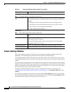
Feature Setup Windows
IO Ports Settings Window
The IO Ports Settings window lets you configure various options for the two input and two output ports
on the IP camera. A state change of an input ports triggers a camera to take configured actions. Output
ports send signals that can control external devices, such as alarms or door switches.
The IP camera can trigger an action only when the input that is received on an input port comes from a
contact that is in a normally closed condition. The camera triggers the action when the contact changes
to an open condition.
To display the IO Ports Settings window, access the configuration windows as described in the
“Performing the Initial Setup of the IP Camera” section on page 2-5, click Feature Setup, then click
IO Ports.
If you change the option in this window, you must click the Save Settings button to save the change. If
you do not click this button, changes are not retained when you exit the window. Save Settings appears
at the bottom of the window. You may need to scroll down to it.
Table 3-5 describes the option in the IO Ports Settings window.
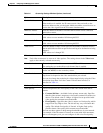
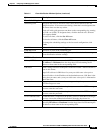
Display Text If you check the Enable Text Display check box, the text that you enter in
this field appears as an overlay on the video image from the IP camera.
The text can contain up to 26 characters, which can include letters, numbers,
spaces, and these characters:
! $ % ( ) + , - . / : = @ ^ _ ` { } ~
Table 3-4 Video Overlay Settings Window Options (continued)
Option Description
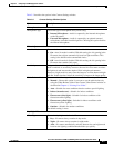
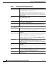
Ta b l e 3-5 IO Ports Settings Window Options
Option Description
Input Ports Area
Port # Display only. Indicates input port 1 and input port 2.
Current State Display only. Indicates the current state (high or low) of the corresponding
port.
Event Trigger Choose the state (Rising or Falling) that triggers designated camera actions.
When an input port changes to the configured state, the camera determines
that an event has occurred and takes the actions that you have configured.
Output Ports
Port # Display only. Indicates output port 1 and output port 2.
Current State Display only. Indicates the current state (high or low) of the corresponding
port.
Default State Choose the state (low or high) that the corresponding port is set to when the
IP camera powers on or resets.
The port changes to this state when you click Save Settings.
The default setting is High.
Event Action Display only. Indicates the current state (high or low) that the output port
changes to when an event occurs.