


2-14
Cisco Video Surveillance 5010/5011 Indoor Fixed HD IP Dome Camera User Guide
OL-22669-02
Chapter 2 Installation
Wiring
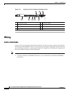
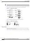
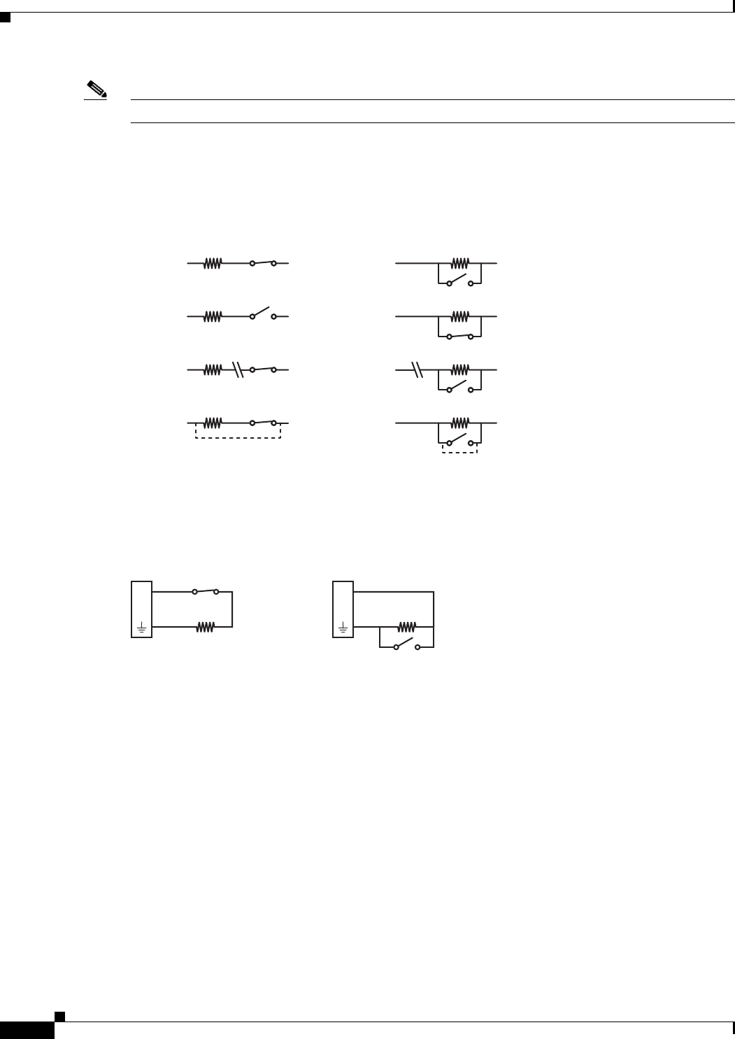
Note Install the 1-kohm resistor as close to the switch as possible.
Figure 2-17 illustrates the alarm and no alarm conditions of a supervised alarm input. Whether the alarm
is normally closed or normally open, neither a cut nor a bypass can defeat these alarms.
Figure 2-17 Supervised Alarm Conditions
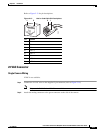
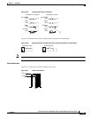
Figure 2-18 illustrates the wiring configuration for supervised alarm inputs.
Figure 2-18 Supervised Alarm Input Wiring
Unsupervised Alarms
When an alarm is configured as an unsupervised alarm, the camera only activates an alarm when the
normal alarm state (open or closed) changes.
Figure 2-19 on page 2-15 illustrates the alarm and no alarm conditions of an unsupervised alarm input.
+V
+V
+V
+V
+V
+V
+V
+V
Bypass
CUT
Bypass
CUT
1 KΩ
1 KΩ
1 KΩ
1 KΩ
1 KΩ
1 KΩ
1 KΩ
1 KΩ
GND
Alarm
GND
Alarm
GND
No Alarm
GND
Alarm
GND
Alarm
GND
Alarm
GND
No Alarm
GND
Alarm
Normally OpenNormally Closed
278791
1 KΩ
A1
1 KΩ
A1
Normally OpenNormally Closed
278789