


7-16
Cisco PIX Security Appliance Hardware Installation Guide
78-15170-03
Chapter 7 PIX535
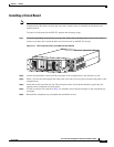
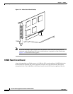
Installing a Circuit Board in the PIX 535
Circuit Board Slot Description
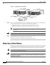
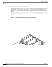
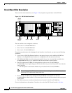
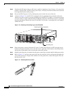
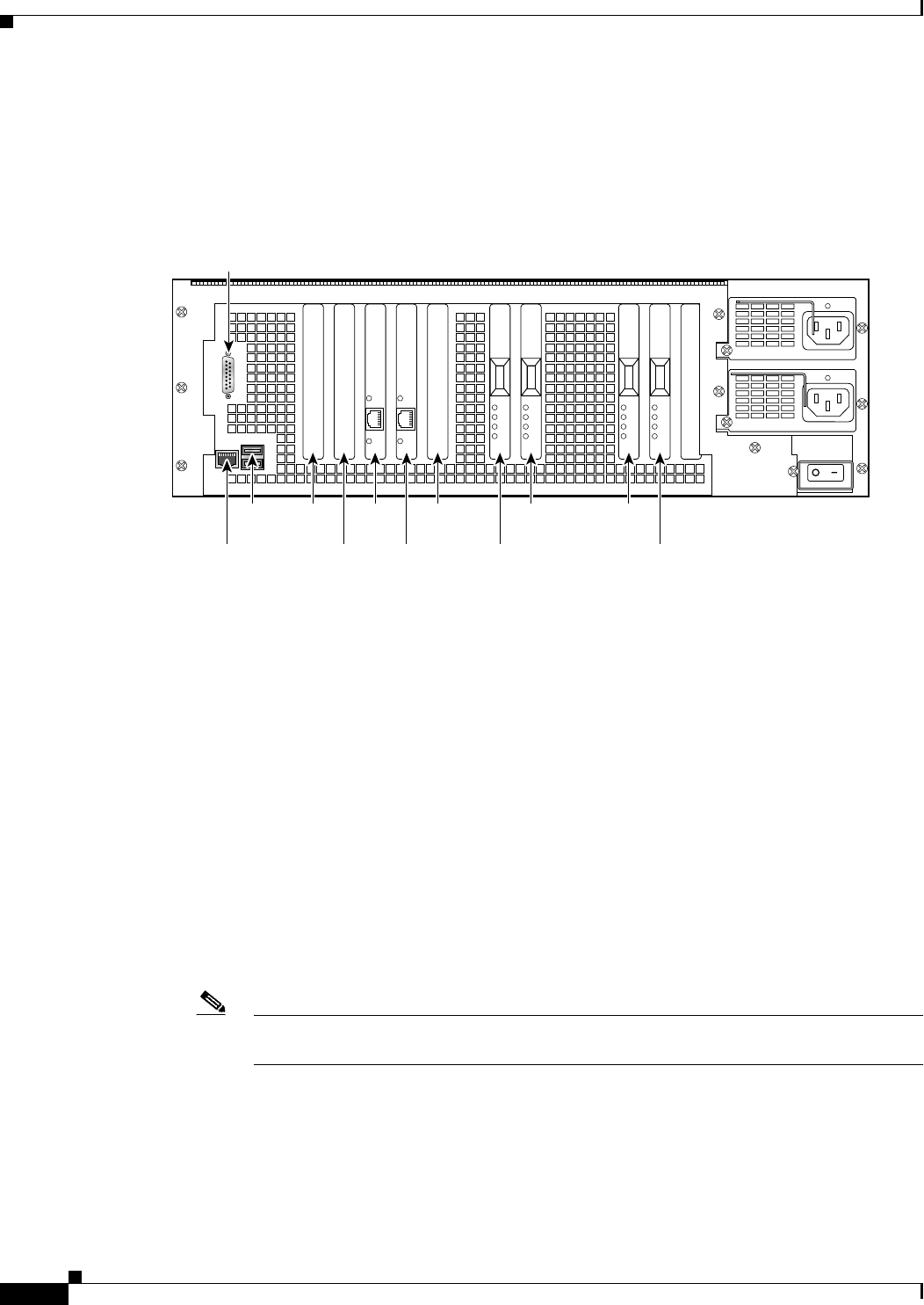
There are nine circuit board slots (see Figure 7-10) using three separate buses for the PIX 535.
Figure 7-10 PIX 535 Back Panel Detail
The slots and buses are configured as follows:
• Slots 0 and 1—64-bit/66 MHz Bus 0
• Slots 2 and 3—64-bit/66 MHz Bus 1
• Slots 4 to 8—32-bit/33 MHz Bus 2
For optimum performance and throughput for the interface circuit boards, you must use the following
guidelines:
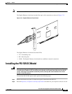
• A total of two 10/100 Fast Ethernet interfaces, and support for up to twelve additional 10/100 Fast
Ethernet or nine Gigabit Ethernet interfaces are configurable with the unrestricted license
• PIX-1GE-66 (66 MHz) circuit boards can be installed in any slot, but should be installed in the
64-bit/66 MHz Bus first. Up to eight PIX-1GE-66 circuit boards can be installed.
• The FE circuit board (33 MHz) can be installed in any bus or slot (32-bit/33 MHz or
64-bit/66 MHz). Up to eight single-port FE circuit boards or up to two four-port FE circuit boards
can be installed.
–
The four-port FE circuit board should only be installed in the 32-bit/33 MHz Bus.
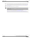
Note The numbering of the FE circuit boards in monitor mode begins at the 32-bit slots; do not
install any FE circuit boards in the 64-bit slots.
• Do not mix the 33 MHz circuit boards with the 66 MHz GE circuit boards on the same
64-bit/66 MHz bus (Bus 0 or Bus 1). The overall speed of the bus will be reduced by the lower speed
circuit board.
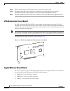
• The VPN Accelerator circuit board should only be installed in the 32-bit/33 MHz Bus.
For more information on the number of interfaces for each of the PIX Firewall models, click here.
61919
Slot 1
Slot 0
Slot 6Slot 8
Slot 7Console
RJ-45
DB-15
failover
USB
port
Slot 4
Slot 5
Slot 2
Slot 3