


2-8
Cisco Video Surveillance 6020 IP Camera Installation Guide
OL-28120-02
Chapter 2 Camera Installation
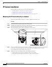
IP Camera Installation
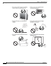
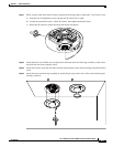
Step 6 Connect a shielded twisted pair (STP) Category 5 or higher network cable to the LAN port on the back
of the camera through the cutout in the camera housing. Connect the other end of the network cable to
a 10/100/BaseT router or switch.
If your network provides PoE, the IP camera powers on.
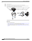
Step 7 (Optional) Connect the following cables to the GPIO terminal block on the IP camera through the cutout
in the camera housing:
• External power cable to the GPIO terminal block if PoE is not available.
• (Optional) I/O cables for external input or out put devices, such as sensors or alarms, to the GPIO
terminal block
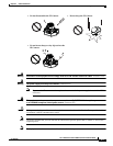
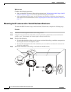
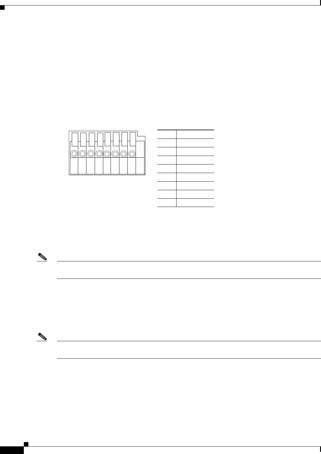
The GPIO terminal block pin locations and descriptions are as follows:
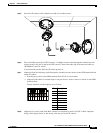
Step 8 Replace the ceiling tile with the camera installed.
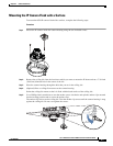
Step 9 (Optional) Use a mini cable with BNC connector to temporarily attach an NTSC or PAL compliant
analog video display device to the analog video out port on the IP camera.
You may need to temporarily remove and adjacent ceiling tile to access the analog video out port.
Note The mini cable with BNC adapter is included in the audio/video cables accessory kit, which you can
purchase from Cisco (Cisco part number CIVS-AVCABLE).
Analog video is enabled by default to allow you to adjust the camera field of view during installation.
However, it is not supported as a normal camera feed and is automatically disabled when any of the
following camera settings are made:
• The primary video stream frame rate must be set higher than 15 fps.
• The secondary video stream must is enabled.
Note We recommend that you disable analog video after installation. To disable analog video, see the Cisco
Video Surveillance 6000 Series IP Camera Configuration Guide.
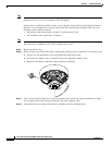
Step 10 Remove the black cover.
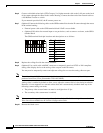
Pin Description
1 12 VDC-
2 12 VDC+
3 24 VAC
4 24 VAC
5 DI-
6 DI+
7 DO-
8 DO+
87654321