


2-11
Cisco Video Surveillance 6020 IP Camera Installation Guide
OL-28120-02
Chapter 2 Camera Installation
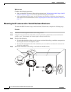
IP Camera Installation
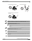
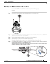
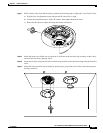
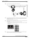
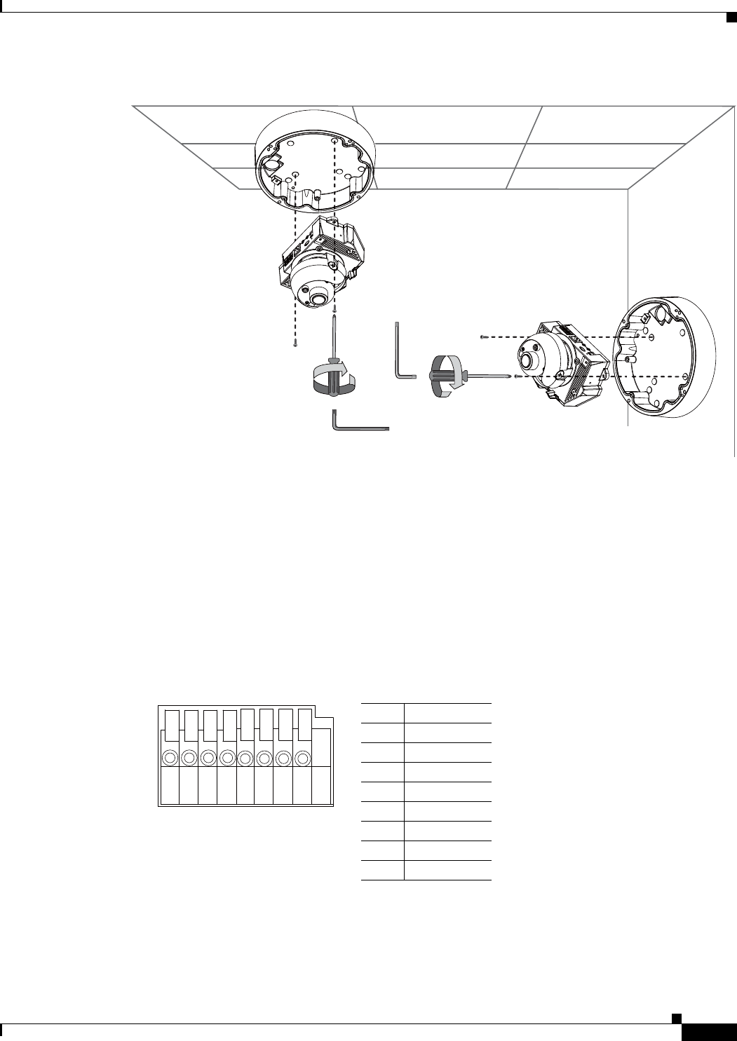
Step 5 Secure the IP camera to the conduit base with two included screws.
Step 6 Feed a shielded twisted pair (STP) Category 5 or higher network cable through the conduit base and
connect to the LAN port on the back of the camera. Connect the other end of the network cable to a
10/100/BaseT router or switch.
If your network provides PoE, the IP camera powers on.
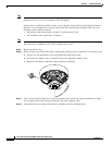
Step 7 (Optional) Feed the following cables through the conduit base and connect to the GPIO terminal block
on the IP camera:
• External power cable to the GPIO terminal block if PoE is not available.
• (Optional) I/O cables for external input or out put devices, such as sensors or alarms, to the GPIO
terminal block
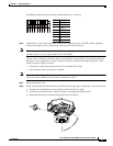
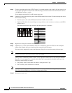
The pin locations and descriptions are as follows:
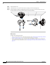
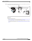
Step 8 (Optional) Use a mini cable with BNC connector to temporarily attach an NTSC or PAL compliant
analog video display device to the analog video out port on the IP camera.
Pin Description
1 12 VDC-
2 12 VDC+
3 24 VAC
4 24 VAC
5 DI-
6 DI+
7 DO-
8 DO+
87654321