


2-4
Cisco Video Surveillance 2500 Series IP Camera User Guide
OL-19273-02
Chapter 2 Getting Started
Installing the Cisco Video Surveillance IP Camera
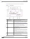
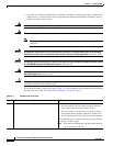
Step 10
If you are using a wireless IP camera, or a wired IP
camera on a network connection that does not provide
PoE, connect the optional 12 V power adapter.
First, connect the bare wires at the end of the power
adapter to the terminal block that is provided with the IP
camera:
• With the screws on the terminal block facing down,
put the positive wire into the slot at the right rear of
the terminal block and put the negative wire into the
slot on the left. (On the Cisco power adapter, the
positive wire has a white stripe and the negative wire
has no stripe.)
• Use a small flat-head screwdriver to tighten the
screws on the bottom of the terminal block so that the
power adapter wires are attached securely.
Note The power adapter may include an attached
terminal block that does not fit the IP camera. If
so, remove that terminal block and replace it with
the one that is provided with the IP camera.
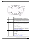
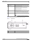
Next, plug the terminal block into the power input port on
back of the IP camera. The terminal block fits into the
input port in one way. Make sure that the tabs on the
terminal block face the bottom of the IP camera.
Finally, plug the power adapter into an electrical outlet.
The IP camera powers up.
Step 11
Check the LEDs on the IP camera.
• The Ready LED blinks while the IP camera starts up.
After 15 to 20 seconds, startup completes and the
Ready LED should remain on.
• The Network LED should be on.
Step 12
Wireless model only: If you connected the IP camera to
a router, switch, or Ethernet port on a PC as described in
Step 9, configure wireless settings, then power down the
IP camera, disconnect the network cable, and power up
the IP camera.
Connect to the IP camera as described in the Performing
the Initial Setup of the IP Camera, page 2-5, then
configure wireless settings as described in Chapter 3,
“Configuring and Managing the IP Camera.” At a
minimum, you must configure the service set identifier
(SSID) in the Basic Setup window.
After configuring, disconnect the power cable and the
network cable, then reconnect the power cable. After the
IP camera powers up, make sure that the Ready LED and
Network LED are on.
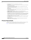
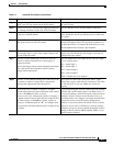
Step 13
Mount the IP camera in the desired location. Connect the mounting device to the threaded mounting
hole on the bottom or top of the IP camera, depending on
your installation requirement.
You may first need to remove the rubber protector from the
mounting hole. Place this protector in the unused
mounting hole.
Step 14
Optional. Use the lockdown cable slot to secure the IP
camera.
You can secure the IP camera to a fixed object by using
Kensington-compatible lockdown equipment
Table 2-1 Installing the IP Camera (continued)
Action Explanation