


2-7
Cisco Video Surveillance System 2621 IP Dome User Guide
OL-24129-02
Chapter 2 Getting Started
Installing the Cisco Video Surveillance 2621 IP Dome
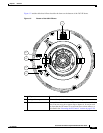
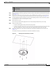
Step 8 (Optional) Use the GPIO ports to connect external devices that trigger alarms (connect through alarm
input ports) or respond to alarms (connect through alarm output ports). (See
Figure 1-1 on page 1-3.)
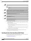
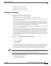
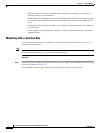
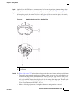
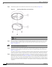
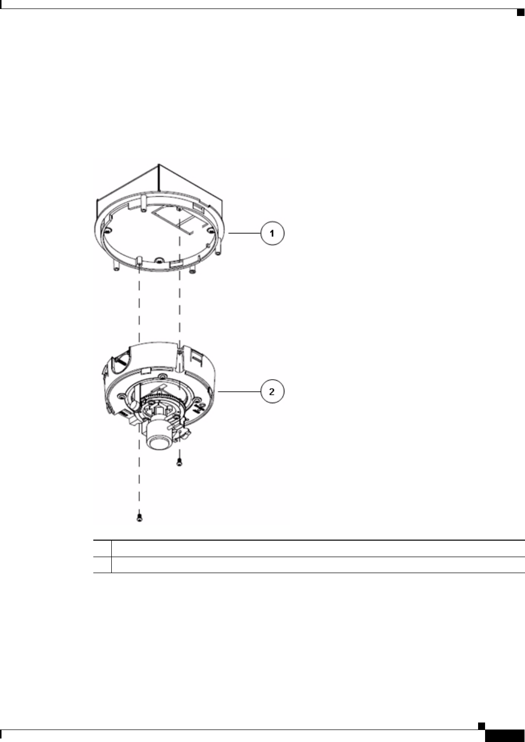
Step 9 Attach the camera unit to the base plate by aligning the three tabs on the camera unit with the slots on
the base plate, pressing the camera unit into the base plate until the tabs snap into place, and securing
the camera unit with the two camera unit screws (see
Figure 2-4).
Figure 2-4 Attaching the Camera Unit to the Base Plate
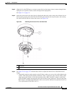
Step 10 See Figure 2-16 on page 2-27 and take these actions to adjust the camera lens to obtain the desired image
• Temporarily attach an analog monitor to the IP dome so that you can see video while adjusting the
camera. If the cable from the monitor terminates with a 3.5 mm jack, plug it into the analog video
output port on the IP dome. If the cable terminates with a BNC connector, connect it to the optional
mini cable with BNC adapter, then plug the cable into the analog video output port. The mini cable
with BNC adapter is included in the audio/video cables accessory kit, which you can purchase from
Cisco (Cisco part number CIVS-IPCA-1017=).
• Make the following adjustments, viewing the video on the analog monitor as needed:
1 Base plate
2 Camera unit