


2-22
Cisco Video Surveillance System 2621 IP Dome User Guide
OL-24129-02
Chapter 2 Getting Started
Installing the Cisco Video Surveillance 2621 IP Dome
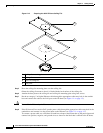
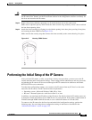
Step 5 Drill 4 holes for screws and cut out the rectangle for cables.
The screw holes should be the appropriate size for the mounting hardware that you are using.
Step 6 Attach the base plate to the surface by using four screws that are appropriate for the surface.
Use anchors if necessary and make sure to attach the conduit base securely.
Step 7 Put the an category 5 or higher Ethernet cable through the appropriate cable entry hole in the conduit
base and connect the cable to the LAN port on the IP dome (see
Figure 1-1 on page 1-3).
Caution Do not lift the IP dome by the Ethernet cable.
Step 8 If the IP dome will not receive PoE, put the power cable through the appropriate cable entry hole in the
conduit base and connect it to the power input on the IP dome (see
Figure 1-1 on page 1-3).
To connect a power cable, use a flat-head screwdriver to depress the brown tabs on the power input and
connect bare positive, negative, and ground wires as shown on the label that is affixed to the IP dome.
Step 9 (Optional) Connect an external speaker, microphone, or both to the Y cable, then connect the Y cable to
the audio port on the IP dome.(see
Figure 1-1 on page 1-3). The Y cable that is included in the optional
audio/video cables accessory kit can be purchased from Cisco (Cisco part number CIVS-IPCA-1017=).
Each device connects to the audio cable through a standard 3.5 mm mini phone jack. A speaker connects
to the green jack, which is labeled “Audio Out.” A microphone connects to the pink jack, which is labeled
“Audio In.”
Step 10 (Optional) Use the GPIO ports to connect external devices that trigger alarms (connect through alarm
input ports) or respond to alarms (connect through alarm output ports).
See Figure 1-1 on page 1-3).
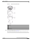
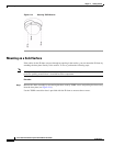
Step 11 Attach the camera unit to the base plate by aligning the three tabs on the camera unit with the slots on
the base plate, pressing the camera unit into the base plate until the tabs snap into place, and securing
the camera unit with the two camera unit screws.
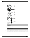
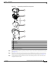
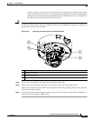
Step 12 See Figure 2-16 on page 2-27 and take these actions to adjust the camera lens to obtain the desired image
• Temporarily attach an analog monitor to the IP dome so that you can see video while adjusting the
camera. If the cable from the monitor terminates with a 3.5 mm jack, plug it into the analog video
output port on the IP dome. If the cable terminates with a BNC connector, connect it to the mini
cable with BNC adapter, then plug the cable into the analog video output port. The mini cable with
BNC adapter is included in the audio/video cables accessory kit, which you can purchase from Cisco
(Cisco part number CIVS-IPCA-1017=).
• Make the following adjustments, viewing the video on the analog monitor as needed:
–
Back focus—The back focus is factory set for optimal use and should not require adjustments.
In the event that it does need to be adjusted, use the 0.9 mm Allen wrench that is supplied with
the IP camera to loosen the three back focus hex screws, then adjust the back focus by aiming
the IP camera at an object that is at least 15 feet (4.5 meters) away and gently sliding the lens
toward or away from the camera. Take care not to pull the lens completely away from the
camera. Obtain a sharp picture in both wide-angle and telephoto positions. When the focus is
set as desired, use the Allen wrench to tighten the three back focus hex screws.
–
Pan—Use a Phillips-head screwdriver to loosen the panning lock screw, then rotate the camera
to obtain the desired image, then tighten the panning lock screw.
–
Tilt—Loosen the two tilt lock screws, adjust the lens to obtain the desired image, then tighten
the screws.