


36-7
User Guide for Cisco Security Manager 4.4
OL-28826-01
Chapter 36 Managing IPS Device Interfaces
Configuring Interfaces
Field Reference
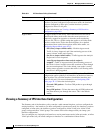
Table 36-1 IPS Interfaces Policy
Element Description
Physical Interfaces tab The physical interfaces that are available on the device. You can edit
these interfaces only (select the device and click the Edit Row button);
you must perform inventory discovery on the device to obtain the
correct list of physical interfaces, for example, if you add an interface
card to the device.
The columns displayed on the tab show the configuration of each
interface and are explained in Modify Physical Interface Map Dialog
Box, page 36-11. Note that the Administrative State column indicates
whether the interface is enabled (Yes or No); you must enable an
interface for it to function.
For more information, see Configuring Physical Interfaces, page 36-10.
Inline Pairs tab The inline interface pairs that allow inline mode processing, as
described in Inline Interface Mode, page 36-3. The table shows the
name of the pair, the interfaces that are part it, and a description, if any.
For more information, see Configuring Inline Interface Pairs,
page 36-13.
• To add a pair, click the Add Row button and fill in the Add
Interface Pair dialog box.
• To edit a pair, select it and click the Edit Row button.
• To delete a pair, select it and click the Delete Row button.
VLAN Pairs tab The VLAN pairs for each physical interface, as described in Inline
VLAN Pair Mode, page 36-3. The table shows the interface and
subinterface, with the two VLANs that are paired, and a description, if
any. For more information, see Configuring Inline VLAN Pairs,
page 36-14.
• To add a pair, click the Add Row button and fill in the Add VLAN
Pair dialog box.
• To edit a pair, select it and click the Edit Row button.
• To delete a pair, select it and click the Delete Row button.
VLAN Groups tab The VLAN groups defined for a physical interface or inline pair, as
described in VLAN Group Mode, page 36-4. The table shows the name
of the interface or pair, the VLAN group (empty means all unassigned
VLANs), and a description, if any. For more information, see
Configuring VLAN Groups, page 36-15.
• To add a group, click the Add Row button and fill in the Add
VLAN Group dialog box.
• To edit a group, select it and click the Edit Row button.
• To delete a group, select it and click the Delete Row button.