


40-11
User Guide for Cisco Security Manager 4.4
OL-28826-01
Chapter 40 Managing IPS Anomaly Detection
Configuring Anomaly Detection
Configuring Anomaly Detection Thresholds and Histograms
Anomaly detection uses thresholds and histograms to determine if scanning behavior is an attack. In
most cases, you can use the default thresholds and the histograms that anomaly detection generates
during learning mode (see Anomaly Detection Modes, page 40-2). However, you might want to fine-tune
these settings. Changing the thresholds is a more likely change than creating your own histograms.
Before you configure these settings, read Understanding Anomaly Detection Thresholds and
Histograms, page 40-9. You must understand how thresholds and histograms are used together to
configure them.
Step 1 Do one of the following to open the Anomaly Detection policy you want to modify:
• (Device view) Select IPS > Anomaly Detection from the Policy selector.
• (Policy view) Select IPS > Anomaly Detection from the Policy selector. Select an existing policy
or create a new one.
Step 2 Click the tab for the zone whose thresholds or histograms you want to change. You configure separate
values for each zone: Internal Zone, Illegal Zone, External Zone. For an explanation of the zones, see
Anomaly Detection Zones, page 40-3.
The tabs for each zone contain four sub-tabs: General, TCP Protocol, UDP Protocol, and Other
Protocols. The General tab defines the IP addresses for the zone and whether the zone is enabled (the
External zone includes all IP addresses not specified for the other zones, you do not configure specific
addresses for the External zone).
The other tabs are where you define thresholds and histograms.
Step 3 Select the tab for the protocol for which you want to modify thresholds or histograms: TCP Protocol,
UDP Protocol, Other Protocol.
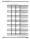
On each tab, configure the following options:
• Enabled—Whether anomaly detection is enabled for the protocol. You can turn off detection for all
of TCP, UDP, or for all non-TCP/UDP protocols with this option. If you deselect the option, any
other settings configured on the tab are ignored.
• Destination Port Map or Protocol Number Map table—This table lists the TCP/UDP ports, or
other protocols, for which you are configuring non-default mappings. By default, all ports and
protocols are enabled and use the default scanner threshold.
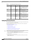
Add items to this table only if you want to: disable detection for a port or protocol; set a different
threshold value for a port or protocol; or configure an explicit histogram for a port or protocol, which
will be used instead of the learned histogram.
–
To add a mapping, click the Add Row (+) button and fill in the Add Dest or Protocol Map dialog
box. For detailed information, see Dest Port or Protocol Map Dialog Box, page 40-12.
–
To edit a mapping, select it and click the Edit Row (pencil) button.
–
To delete a mapping, select it and click the Delete Row (trash can) button. Deleting a mapping
returns the service to the default settings.
• Scanner Threshold—The threshold for all TCP, UDP, or other protocols. This threshold is used for
all services except those for which you configured a scanner override in the mapping table. The
range is 5 to 1000. The default is 200.
• Threshold Histogram—The default histogram for all TCP, UDP, or other protocols. This histogram
is used for all services except those for which you configured a scanner override in the mapping
table.