


45-19
User Guide for Cisco Security Manager 4.4
OL-28826-01
Chapter 45 Managing Firewall Devices
Configuring Firewall Device Interfaces
• Use DHCP – Enables Dynamic Host Configuration Protocol (DHCP) for automatic assignment of
an IP address from a DHCP server on the connected network. The following options become
available:
–
Obtain Default Route using DHCP – Check this box to obtain a default route from the DHCP
server so that you do not need to configure a default static route.
–
Retry Count – The number of times the PIX will resend the DHCP request. Valid values are 4
to 16; the default is 2
• PPPoE (PIX and ASA 7.2+) – This option does not apply to PIX 6.3 devices.
Note You can configure DHCP only on the outside interface of a firewall device.
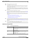
Add/Edit Interface Dialog Box (PIX 7.0+/ASA/FWSM)
These Add Interface and Edit Interface dialog boxes are used to define and configure interfaces,
subinterfaces, redundant, and EtherChannel interfaces on PIX 7.0+, ASA, and FWSM devices. You can
access the Add/Edit Interface dialog boxes from the Interfaces page. See Managing Device Interfaces,
Hardware Ports, and Bridge Groups, page 45-14 for more information.
Note The ASA 5505, combining switch and security appliance features, is a special case in that you configure
both physical switch ports and logical VLAN interfaces. Thus, the Interfaces page displayed for ASA
5505 devices presents two tabbed panels: Hardware Ports and Interfaces. See Understanding ASA
5505 Ports and Interfaces, page 45-6 for more information.
ASA 8.4.1+ and FWSM 3.1+ devices operating in transparent mode also present two tabbed panels:
Interfaces and Bridge Groups. See Add/Edit Bridge Group Dialog Box, page 45-41 for information
about configuring bridge groups.
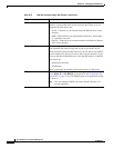
Many of the parameters presented in these dialog boxes vary according to device type and version,
operational mode (routed versus transparent), and whether the device hosts a single or multiple contexts.
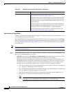
Note If you intend to use an interface for failover, you can define that interface in the Add Interface dialog
box but do not configure it; instead, use the Failover page (see Chapter 49, “Configuring Failover”). In
particular, do not specify an interface Name, as this parameter disqualifies the interface from being used
as the failover link.
Using the Add Interface and Edit Interface Dialog Boxes
The following steps outline the general use of these dialog boxes:
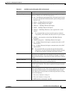
1. An interface Type drop-down list appears at the top of the Add Interface and Edit Interface dialog
boxes.
Note Catalyst 6500 services modules (ASA-SMs and FWSMs) and the ASA 5505 do not present
the Type list.