


45-34
User Guide for Cisco Security Manager 4.4
OL-28826-01
Chapter 45 Managing Firewall Devices
Configuring Firewall Device Interfaces
• From the Management IPv6 page of an ASA 5505 in transparent firewall mode (version 8.2 and 8.3
devices only).
Click the Add Row or Edit Row buttons beneath the table in the Interfaces IPv6 Addresses section to
open the dialog box.
Related Topics
• IPv6 Prefix Editor Dialog Box, page 45-34
• Add/Edit Interface Dialog Box (PIX 7.0+/ASA/FWSM), page 45-19
• Managing Device Interfaces, Hardware Ports, and Bridge Groups, page 45-14
• Management IPv6 Page (ASA 5505), page 46-10
Field Reference
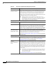
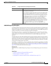
IPv6 Prefix Editor Dialog Box
This dialog box is used to add or edit an IPv6 prefix (that is, the network portion of an IPv6 address),
providing control over individual parameters, including whether the prefix should be included in IPv6
router advertisements. Multiple prefixes can be configured in the IPv6 panel of the ASA or FWSM Add
Interface or Edit Interface dialog box.
Note This dialog box is available only on ASA 7.0+ devices in routed mode; ASA 8.2+ devices in transparent
mode; and FWSM 3.1+ devices in routed mode.
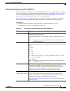
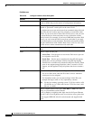
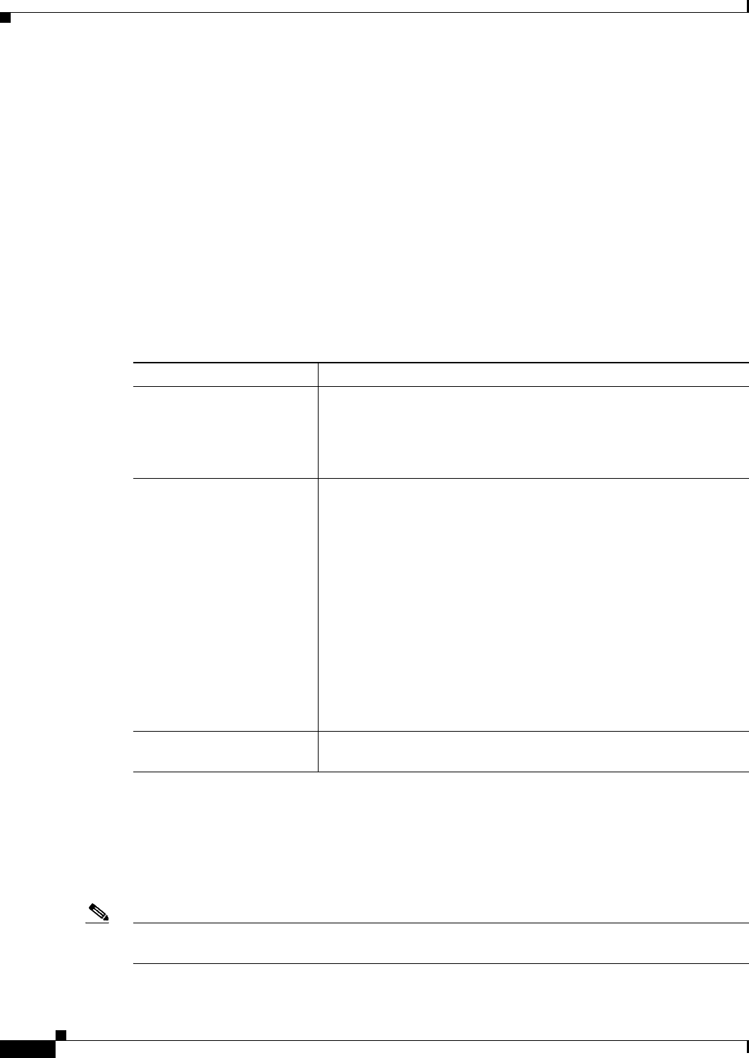
Table 45-6 IPv6 Address for Interface Dialog Box
Element Description
Address/Prefix Length Enter an IPv6 network address to be assigned to the interface, with its
Prefix Length appended, where the Prefix Length integer indicates how
many of the high-order, contiguous bits of the address comprise
network portion of the address. A slash (/) must precede the Prefix
Length. For example, 3FFE:C00:0:1::/64.
EUI-64 If this box is checked, the EUI-64 interface ID will be used in the
low-order 64 bits of the IPv6 address. If the value specified for the
Prefix Length is greater than 64 bits, the prefix bits have precedence
over the interface ID. An error occurs if another host is using the
specified address.
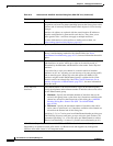
The Modified EUI-64 format interface ID is derived from the 48-bit
link-layer (MAC) address by inserting the hex number FFFE between
the upper three bytes (OUI field) and the lower 3 bytes (serial number)
of the link layer address. To ensure the chosen address is from a unique
Ethernet MAC address, the next-to-lowest order bit in the high-order
byte is inverted (universal/local bit) to indicate the uniqueness of the
48-bit address. For example, an interface with a MAC address of
00E0.B601.3B7A would have a 64 bit interface ID of
02E0:B6FF:FE01:3B7A.
IPv6 Address Pool Enter or select the IPv6 Pool object that represents the pool of addresses
to use.