45-37
User Guide for Cisco Security Manager 4.4
OL-28826-01
Chapter 45 Managing Firewall Devices
Configuring Firewall Device Interfaces
In multiple-context mode, interface IP addresses are set in the context configuration.
Note Do not use addresses previously used for routers, hosts, or any other firewall device commands, such as
an IP address in the global pool or a static NAT entry.
Also, do not specify IP Type information for an interface you intend to use as a redundant interface.
Step 1 In the Add/Edit Interface dialog box, choose a method for address assignment (Static IP, Use DHCP, or
PPPoE (PIX and ASA 7.2+)) from the IP Type list, and then provide related parameters, as follows:
• Static IP – Provide a static IP Address and Subnet Mask that represents the security device on this
interface’s connected network. The IP address must be unique for each interface.
The Subnet mask can be expressed in dotted decimal format (for example, 255.255.255.0), or by
entering the number of bits in the network mask (for example, 24). Do not use 255.255.255.254 or
255.255.255.255 for an interface connected to the network because this will stop traffic on that
interface. If you omit the Subnet Mask value, a “classful” network is assumed, as follows:
–
The Class A netmask (255.0.0.0) is assumed if the first octet of the IP Address is 1 through 126
(i.e., addresses 1.0.0.0 through 126.255.255.255).
–
The Class B netmask (255.255.0.0) is assumed if the first octet of the IP Address is 128 through
191 (i.e., addresses 128.0.0.0 through 191.255.255.255).
–
The Class C netmask (255.255.255.0) is assumed if the first octet of the IP Address is 192
through 223 (i.e., addresses 192.0.0.0 through 223.255.255.255).
Note Do not use addresses previously used for routers, hosts, or any other firewall device
commands, such as an IP address in the global pool or a static NAT entry.
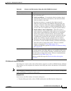
• Use DHCP – Enables Dynamic Host Configuration Protocol (DHCP) for automatic assignment of
an IP address from a DHCP server on the connected network. The following options become
available:
–
DHCP Learned Route Metric (required) – Assign an administrative distance to the learned
route. Valid values are 1 to 255. The administrative distance for learned routes defaults to 1.
All routes have a value or “metric” that represents its priority of use. (This metric is also referred
to as “administrative distance.”) When two or more routes to the same destination are available,
devices use administrative distance to decide which route to use.
–
Obtain Default Route using DHCP – Select this option to obtain a default route from the
DHCP server so that you do not need to configure a default static route. See also Configuring
Static Routes, page 54-48.
–
Enable Tracking for DHCP Learned Route – If Obtain Default Route using DHCP is
selected, you can select this option to enable route tracking via a specific Service Level
Agreement (SLA) monitor. The following option becomes available:
–
Tracked SLA Monitor – Required if Enable Tracking for DHCP Learned Route is selected.
Enter or Select the name of the SLA monitor object that defines the route tracking (connectivity
monitoring) to be applied to this interface. See Monitoring Service Level Agreements (SLAs)
To Maintain Connectivity, page 50-7 for more information.
• PPPoE (PIX and ASA 7.2+) – Enables Point-to-Point Protocol over Ethernet (PPPoE) for
automatic assignment of an IP address from a PPPoE server on the connected network; this option
is not supported with failover. The following options become available:


