


49-20
User Guide for Cisco Security Manager 4.4
OL-28826-01
Chapter 49 Configuring Failover
Failover Policies
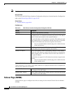
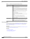
Settings Dialog Box
The Settings dialog box lets you define criteria for when failover should occur on the selected ASA or
PIX 7.x appliance.
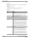
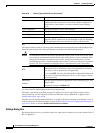
Logical Name Enter the logical name of the interface on the active firewall device to
communicate with standby device for failover. When configured for
stateful failover, the interface is directly connected to the standby
device.
Active IP Address Specify the IP address of the active interface.
Standby IP Address Specify the IP address of the standby interface.
Subnet Mask Enter the Subnet Netmask for the active and standby IP addresses.
Enable HTTP Replication When selected, active HTTP sessions are copied to the standby firewall.
Otherwise, HTTP connections are disconnected at failover. Disabling
HTTP replication reduces the amount of traffic on the state link.
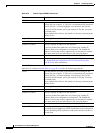
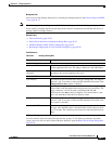
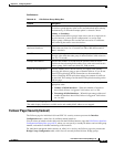
Key
The options in this section let you encrypt the communications between the active and standby devices.
Select the type and provide a string of characters to produce the shared encryption key.
Caution All information sent over the failover and Stateful Failover links is sent in clear text unless
you secure the communication with a failover key. If this device is used to terminate VPN
tunnels, this information includes any user names, passwords and shared keys used for
establishing the tunnels. Transmitting this sensitive data in clear text could pose a significant
security risk. We recommend securing the failover communications with a shared key.
Any string
HEX
If you select Any string, the entry in the Shared Key field can be any
combination of up to 63 numbers, letters and punctuation characters.
This string is used to generate the encryption key.
If you select HEX, the entry in the Shared Key and Confirm fields must
be exactly 32 hexadecimal characters (0-9, a-f). This string is used as
the encryption key.
Shared Key
Confirm
Enter any string of characters appropriate to the selected key type: Any
string or HEX.
Re-enter the string the Confirm field.
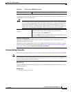
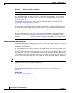
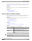
Interface Configuration
(in some instances, labeled Monitor Interface Configuration)
This table is presented on the Failover page for ASA 8.4.1+ devices operating in single-context,
transparent mode, and for individual contexts on PIX/ASA devices. Otherwise, it appears in the
Settings Dialog Box, page 49-20.
The table lists all available named interfaces. To enable or disable monitoring of an interface, select it
in the list and click the Edit Row button to open the Edit Failover Interface Configuration Dialog Box,
page 49-23. Select or deselect Monitor this interface for failure.
Table 49-6 Failover Page (ASA/PIX 7.0+) (Continued)
Element Description