


49-22
User Guide for Cisco Security Manager 4.4
OL-28826-01
Chapter 49 Configuring Failover
Failover Policies
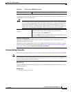
Add/Edit Interface MAC Address Dialog Box
The Add/Edit Interface MAC Address dialog box lets you define virtual MAC addresses for a physical
interface on ASA, FWSM 3.x and PIX 7.x security appliances that are configured for failover (not
available on ASA 5505 devices).
In Active/Standby failover, the MAC addresses for the primary unit are always associated with the active
IP addresses. If the secondary unit boots first and becomes active, it uses the burned-in MAC address for
its interfaces. When the primary unit comes online, the secondary unit obtains the MAC addresses from
the primary unit. This change can disrupt network traffic. You can configure virtual MAC addresses for
each interface to ensure that the secondary unit uses the correct MAC addresses when it is the active unit,
even if it comes online before the primary unit. If you do not specify virtual MAC addresses, the failover
pair uses the burned-in MAC addresses.
Note You cannot configure a virtual MAC address for the failover or Stateful Failover links. The MAC and IP
addresses for those links do not change during failover.
Navigation Path
You can open the Add/Edit Interface MAC Address dialog box from the Settings Dialog Box,
page 49-20.
Related Topics
• Failover Policies, page 49-10
• Failover Page (ASA/PIX 7.0+), page 49-17
• Edit Failover Group Dialog Box, page 49-24
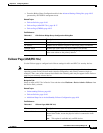
MAC Address Mapping
In Active/Standby mode, this table lists interface-virtual MAC address mappings. This is a standard
Security Manager table, with Add Row, Edit Row and Delete Row buttons, which are described in
Using Tables, page 1-45.
To add or edit interface mappings, click the Add Row or Edit Row button to open the Add/Edit
Interface MAC Address Dialog Box, page 49-22.
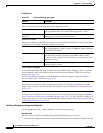
Monitor Interface Configuration
In single-context mode, this table lists all available named interfaces. To define a Standby IP address
for, and enable or disable monitoring of an interface, select it in the list and click the Edit Row button
to open the Edit Failover Interface Configuration Dialog Box, page 49-23.
Management IP Address
In single-context transparent mode, this section presents the management IP address and netmask
defined for the device (on the Management IP Page, page 46-10); you cannot change these values.
Standby Enter the management IP address of the standby unit; this address must
be on the same subnet as the primary address.
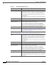
Table 49-7 Settings Dialog Box (Continued)
Element Description