


2-2
Cisco NAC Guest Server Installation and Configuration Guide
OL-15986-01
Chapter 2 Installing Cisco NAC Guest Server
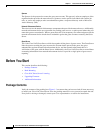
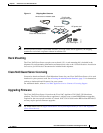
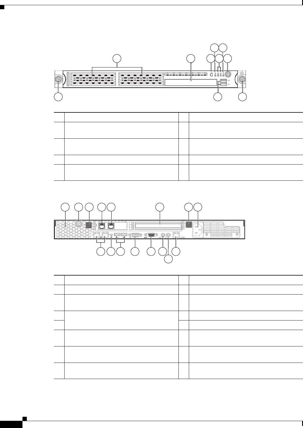
Connecting the Cisco NAC Guest Server
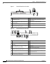
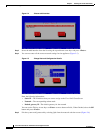
Figure 2-1 Cisco NAC Guest Server Front Panel
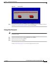
Figure 2-2 Cisco NAC Guest Server Rear Panel
1 2 3
4 6
5 7
8 9 8
180955
1 Hard disk drive (HDD) bay 6 HDD activity LED indicator (green)
2
CD-ROM/DVD drive
7
Power button with LED indicator (bicolor:
green/amber)
3
UID (Unit identification) button with LED
indicator (blue)
8
Thumbscrews for the front bezel
4 System health LED indicator (amber) 9 Front USB ports
5
Activity/link status LED indicators for NIC 1
(eth0) and NIC2 (eth1) (green)
2 31 6 3 7
151312111098
14
180957
54
1 Ventilation holes 9 UID button with LED indicator (blue)
2 Thumbscrew for the top cover 10 Rear USB ports (black)
3
Thumbscrews for the PCI riser board
assembly
11
Video port (blue)
4 NIC 3 (eth2) and NIC 4 (eth3) PCI Express
GbE LAN (RJ-45) ports (Intel)
12 Serial port
5 13 PS/2 keyboard port (purple)
6
Standard height/full-length PCI Express
x16/PCI-X riser board slot cover
14
PS/2 mouse port (green)
7
Power supply cable socket
15
10/100 Mbps iLO LAN port for IPMI
management (RJ-45)
8
NIC 1 (eth0) and NIC 2 (eth1) integrated GbE
LAN (RJ-45) ports (Broadcom)