7-10
Cisco ONS 15600 Reference Manual, R7.2
Chapter 7 Circuits and Tunnels
7.2.5 Circuit Information in the Edit Circuit Window
•
Number of alarms on each node organized by severity
•
Port service states on the circuit route
•
Alarm state/color of most severe alarm on port
•
Loopbacks
•
Path trace states
•
Path selector states
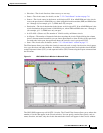
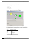
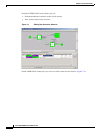
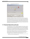
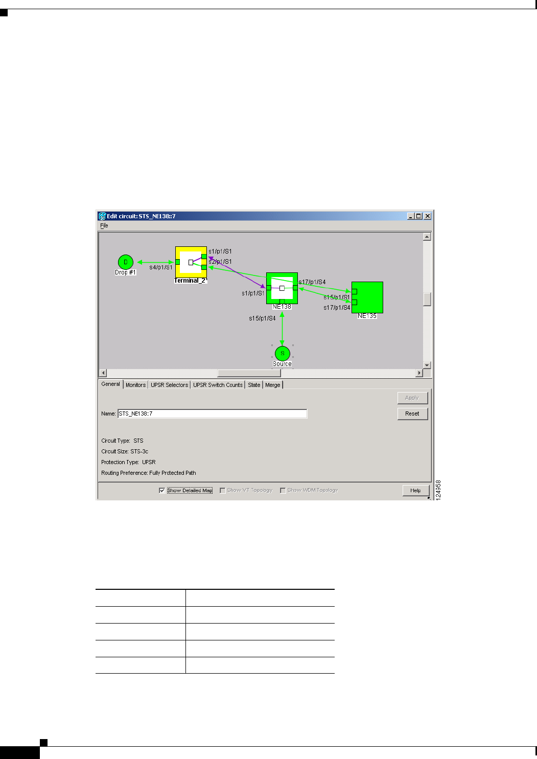
Figure 7-2 shows a bidirectional STS circuit routed on a path protection.
Figure 7-2 Path Protection Circuit on the Edit Circuit Window
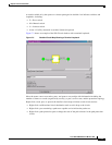
By default, the working path is indicated by a green, bidirectional arrow, and the protect path is indicated
by a purple, bidirectional arrow. Source and destination ports are shown as circles with an S and D,
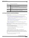
respectively. Port states are indicated by colors, shown in Table 7-4.
Table 7-4 Port State Color Indicators
Port Color Service State
Green IS-NR
Gray OOS-MA,DSBLD
Purple OOS-AU,AINS
Cyan (Blue) OOS-MA,MT


