


7-17
Cisco ONS 15600 Reference Manual, R7.2
Chapter 7 Circuits and Tunnels
7.8.2 BLSR VT Squelch Table
7.8.2 BLSR VT Squelch Table
BLSR VT squelch tables only appear on the node dropping VTs from a BLSR and are used to perform
VT-level squelching when a node is isolated. VT squelching is supported on the ONS 15454 and the
ONS 15327 platforms. The ONS 15600 platform does not support VT squelching; however, when an
ONS 15454 or ONS 15327 and an ONS 15600 are in the same network, the ONS 15600 node allows the
ONS 15454 or ONS 15327 node to carry VT circuits in a VT tunnel. The ONS 15600 performs 100-ms
STS-level squelching for each VT-access STS at the switching node in case of a node failure.
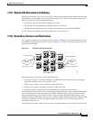
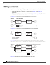
When using a VT circuit on a VT tunnel (VTT), the VTT allows multiple VT circuits to be passed
through on a single STS without consuming VT matrix resources on the cross-connect card. Both
endpoints of the VTT are the source and destination nodes for the VTT. The node carrying VT circuits
through a VTT is called a VT-access node. In case of a source and destination node failure of the VTT,
the switching node performs 100-ms STS-level squelching for the VTT STS. The node dropping VT
traffic performs VT-level squelching. VT traffic on the VTT that is not coming from the failed node is
protected.
When using a VT circuit on a VT aggregation point (VAP), the VAP allows multiple VT circuits to be
aggregated into a single STS without consuming VT matrix resources on the cross-connect card. The
source for each VAP STS timeslot is the STS-grooming end where VT1.5 circuits are aggregated into a
single STS. The destination for each VAP STS is the VT-grooming end where VT1.5 circuits originated.
The source node for each VT circuit on a VAP is the STS-grooming end where the VT1.5 circuits are
aggregated into a single STS. The STS grooming node is not a VT-access node. The non VT-access node
performs STS-level squelching for each STS timeslot at the switching node in case the VT-grooming
node fails. The node dropping VT traffic performs VT-level squelching for each VT timeslot in case the
STS-grooming end node fails. No VT traffic on the VAP is protected during a failure of the
STS-grooming node or the VT-grooming node.
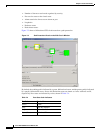
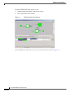
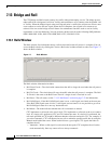
To view the VT squelch table, double-click the VT with a check mark in the BLSR STS squelch table
window. The check mark appears on every VT-access STS; however, the VT-squelch table appears only
by double-clicking the check mark on the node dropping the VT. The intermediate node of the VT does
not maintain the VT-squelch table.
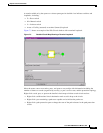
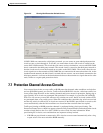
The VT squelch table provides the following information:
•
VT Number—Shows the BLSR VT numbers. The VT number includes VT group number and VT
number in group (VT group 2 and channel 1 are displayed as 2-1.)
•
West Source—If traffic is received by the node on its west span, the BLSR node ID of the source
appears. (To view the BLSR node IDs for all nodes in the ring, click the Ring Map button.)
•
East Source—If traffic is received by the node on its east span, the BLSR node ID of the source
appears.
7.9 Path Trace
SONET J1 path trace is a repeated, fixed-length string that includes 64 consecutive J1 bytes. You can
use the string to monitor interruptions or changes to circuit traffic. If the string received at a circuit drop
port does not match the string the port expects to receive, the Trace Identifier Mismatch Path (TIM-P)
alarm is raised. The ONS 15600 can also monitor a 16-byte ITU pattern.
Table 7-6 lists the ONS 15600 cards that support path trace.