


8-2
Cisco ONS 15600 Reference Manual, R7.2
Chapter 8 SONET Topologies and Upgrades
8.2 Point-to-Point and Linear ADM Configurations
8.2 Point-to-Point and Linear ADM Configurations
You can configure ONS 15600s as a line of add/drop multiplexers (ADMs) by configuring one OC-N
port as the working path and a second port as the protect path. Unlike rings, point-to-point (two node
configurations) and linear (three node configurations) ADMs require that the OC-N ports at each node
are in 1+1 protection to ensure that a break to the working path automatically routes traffic to the protect
path.
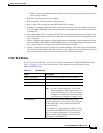
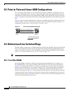
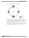
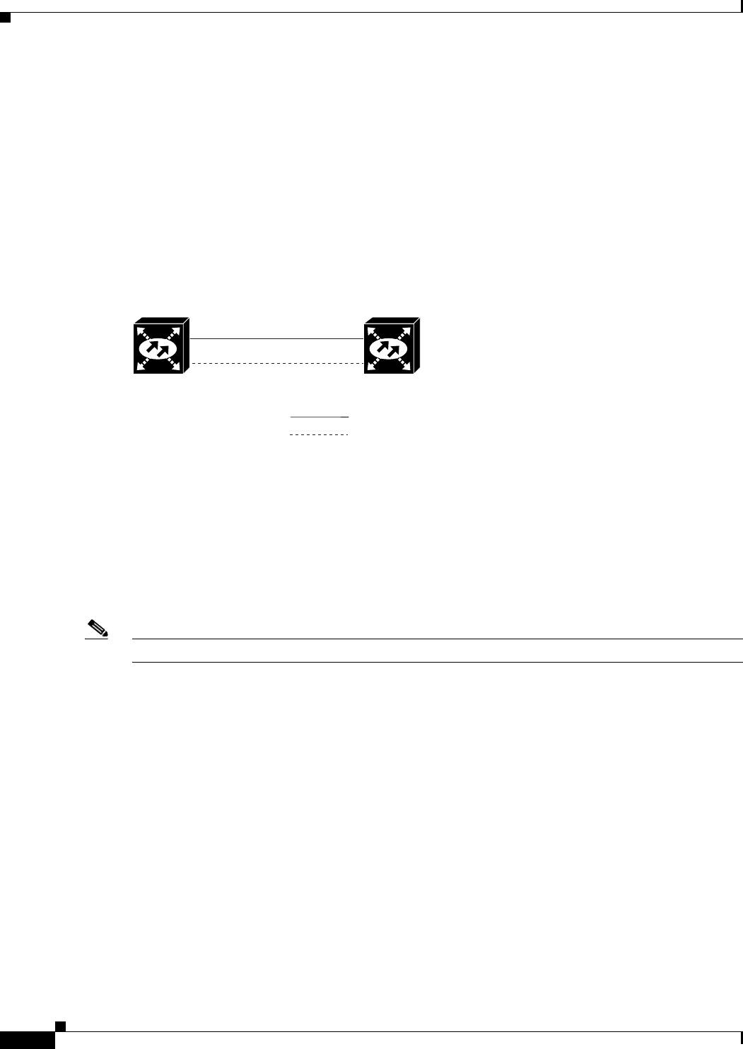
Figure 8-1 shows two ONS 15600 nodes in a point-to-point ADM configuration. Working traffic flows
from Slot 1/Port 1 at Node 1 to Slot 1/Port 1 at Node 2. You create the protect path by creating a 1+1
configuration with Slot 1/Port 1 and Slot 2/Port 1 at Nodes 1 and 2.
Figure 8-1 Point-to-Point ADM Configuration
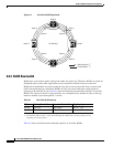
8.3 Bidirectional Line Switched Rings
The ONS 15600 can support up to 32 bidirectional line switched rings (BLSRs). Eight four-fiber BLSR
rings can be supported if all ports are OC-192. Because the working and protect bandwidths must be
equal, you can create only OC-48 or OC-192 BLSRs. For information about BLSR protection channels,
see the “7.7 Protection Channel Access Circuits” section on page 7-15.
Note
For best performance, BLSRs should have one LAN connection for every ten nodes in the BLSR.
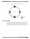
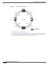
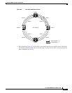
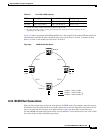
8.3.1 Two-Fiber BLSRs
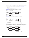
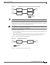
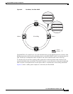
In two-fiber BLSRs, each fiber is divided into working and protect bandwidths. For example, in an
OC-48 BLSR, STSs 1 to 24 carry the working traffic, and STSs 25 to 48 are reserved for protection
(Figure 8-2). Working traffic (STSs 1 to 24) travels in one direction on one fiber and in the opposite
direction on the second fiber. Cisco Transport Controller (CTC) circuit routing routines calculate the
shortest path for circuits based on many factors, including user requirements, traffic patterns, and
distance. For example, in Figure 8-2, circuits going from Node 0 to Node 1 will typically travel on Fiber
1, unless that fiber is full, in which case circuits will be routed to Fiber 2 through Node 3 and Node 2.
Traffic from Node 0 to Node 2 (or Node 1 to Node 3) can be routed on either fiber, depending on circuit
provisioning requirements and traffic loads.
Node 1 Node 2
Slot 1/Port 1 to Slot 1/Port 1
Slot 2/Port 1 to Slot 2/Port 1
Working Path
Protect Path
98292