


8-3
Cisco ONS 15600 Reference Manual, R7.2
Chapter 8 SONET Topologies and Upgrades
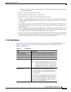
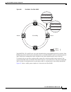
8.3.1 Two-Fiber BLSRs
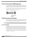
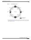
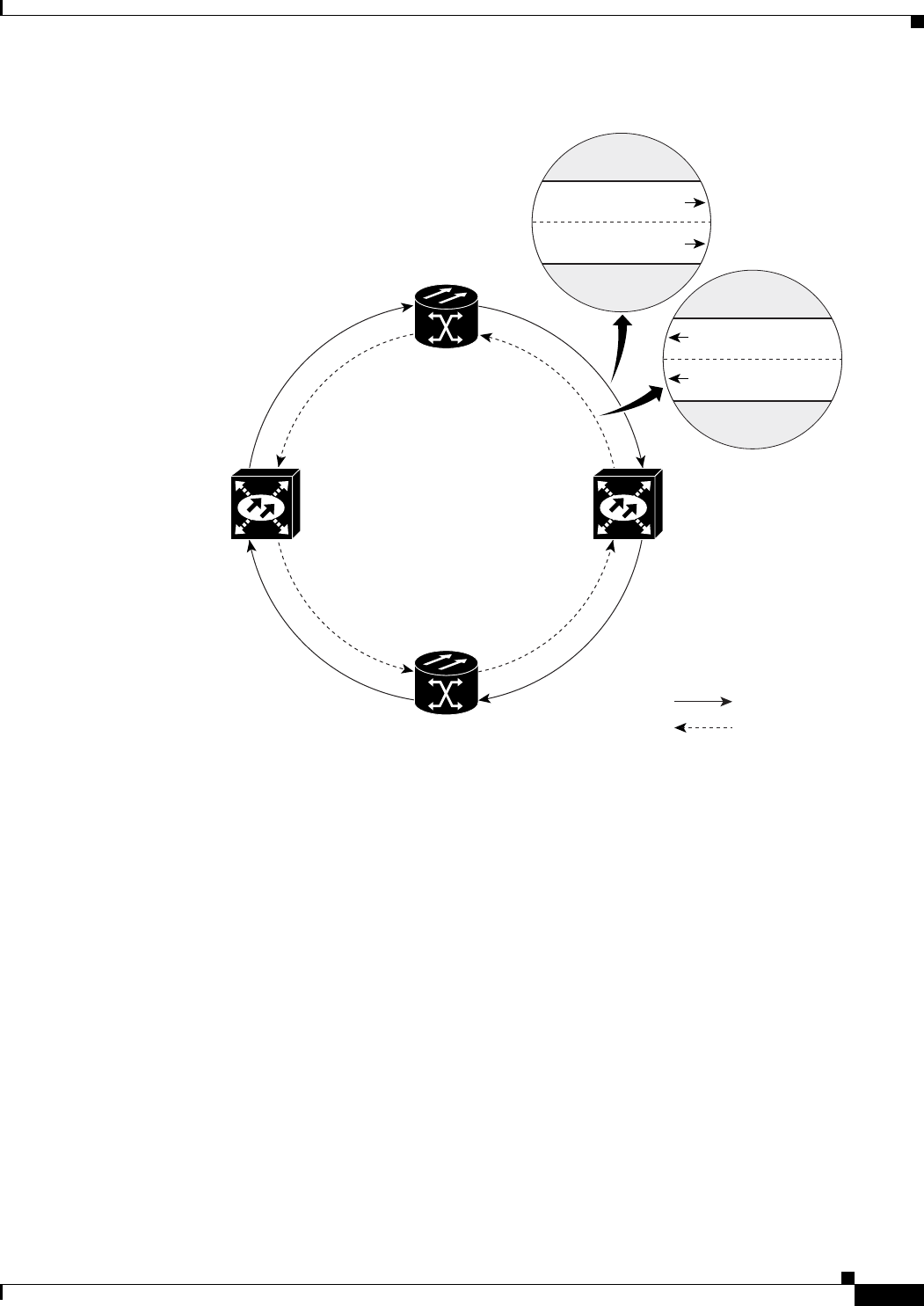
Figure 8-2 Four-Node, Two-Fiber BLSR
The SONET K1, K2, and K3 bytes carry the information that governs BLSR protection switches. Each
BLSR node monitors the K bytes to determine when to switch the SONET signal to an alternate physical
path. The K bytes communicate failure conditions and actions taken between nodes in the ring.
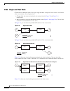
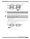
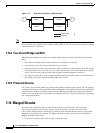
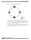
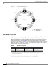
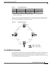
If a break occurs on one fiber, working traffic targeted for a node beyond the break switches to the
protect bandwidth on the second fiber. The traffic travels in a reverse direction on the protect bandwidth
until it reaches its destination node. At that point, traffic is switched back to the working bandwidth.
Figure 8-3 shows a traffic pattern sample on a four-node, two-fiber BLSR.
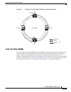
Node 0
Node 1
Node 2
Node 3 OC-48 Ring
= Fiber 1
= Fiber 2
96671
STSs 1-24 (working)
STSs 25-48 (protect)
STSs 1-24 (working)
STSs 25-48 (protect)