


9-24
Cisco ONS 15600 Reference Manual, R7.2
Chapter 9 Management Network Connectivity
9.6 Open GNE
access-list 100 remark *** Inbound ACL, CTC -> NE ***
access-list 100 remark
access-list 100 permit tcp host 192.168.10.10 host 10.10.10.100 eq www
access-list 100 remark *** allows initial contact with the 15600 using http (port 80) ***
access-list 100 remark
access-list 100 permit tcp host 192.168.10.10 host 10.10.10.100 eq 1080
access-list 100 remark *** allows CTC communication with the 15600 GNE (port 1080) ***
access-list 100 remark
access-list 101 remark *** Outbound ACL, NE -> CTC ***
access-list 101 remark
access-list 101 permit tcp host 10.10.10.100 host 192.168.10.10 established
access-list 101 remark *** allows ACKs from the 15600 GNE to CTC ***
9.6 Open GNE
The ONS 15600 can communicate with non-ONS nodes that do not support point-to-point protocol
(PPP) vendor extensions or OSPF type 10 opaque link-state advertisements (LSA), both of which are
necessary for automatic node and link discovery. An open GNE configuration allows the DCC-based
network to function as an IP network for non-ONS nodes.
To configure an open GNE network, you can provision SDCC and LDCC terminations to include a
far-end, non-ONS node using either the default IP address of 0.0.0.0 or a specified IP address. You
provision a far-end, non-ONS node by checking the “Far End is Foreign” check box during SDCC and
LDCC creation. The default 0.0.0.0 IP address allows the far-end, non-ONS node to provide the IP
address; if you set an IP address other than 0.0.0.0, a link is established only if the far-end node identifies
itself with that IP address, providing an extra level of security.
By default, the proxy server only allows connections to discovered ONS peers and the firewall blocks
all IP traffic between the DCC network and LAN. You can, however, provision proxy tunnels to allow
up to 12 additional destinations for SOCKS version 5 connections to non-ONS nodes. You can also
provision firewall tunnels to allow up to 12 additional destinations for direct IP connectivity between
the DCC network and LAN. Proxy and firewall tunnels include both a source and destination subnet.
The connection must originate within the source subnet and terminate within the destination subnet
before either the SOCKS connection or IP packet flow is allowed.
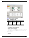
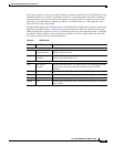
To set up proxy and firewall subnets in CTC, use the Provisioning > Network > Proxy and Firewalls
subtabs. The availability of proxy and/or firewall tunnels depends on the network access settings of the
node:
•
If the node is configured with the proxy server enabled in GNE or ENE mode, you must set up a
proxy tunnel and/or a firewall tunnel.
•
If the node is configured with the proxy server enabled in proxy-only mode, you can set up proxy
tunnels. Firewall tunnels are not allowed.
•
If the node is configured with the proxy server disabled, neither proxy tunnels or firewall tunnels
are allowed.
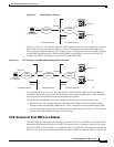
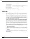
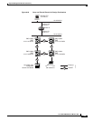
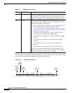
Figure 9-18 shows an example of a foreign node connected to the DCC network. Proxy and firewall
tunnels are useful in this example because the GNE would otherwise block IP access between the PC
and the foreign node.