


CHAPTER
1-1
Cisco ONS 15600 Reference Manual, R7.2
1
Shelf and Backplane Hardware
This chapter provides a description of Cisco ONS 15600 shelf and backplane hardware. Card and cable
descriptions are provided in Chapter 2, “Card Reference.”
To install equipment, refer to the Cisco ONS 15600 Procedure Guide.
Chapter topics include:
•
1.1 Installation Overview, page 1-1
•
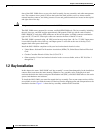
1.2 Bay Installation, page 1-2
•
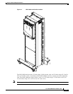
1.3 Front Door, page 1-4
•
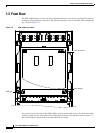
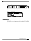
1.4 Rear Covers, page 1-5
•
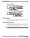
1.5 Cable Routing, page 1-7
•
1.6 Customer Access Panel, page 1-7
•
1.7 Alarm, Timing, LAN, and Craft Pin Connections, page 1-10
•
1.8 Power Distribution Unit, page 1-13
•
1.9 Power and Ground Description, page 1-13
•
1.10 Fan-Tray Assembly, page 1-15
•
1.11 Cards and Slots, page 1-17
Note
The Cisco ONS 15600 assembly is intended for use with telecommunications equipment only.
Note
The ONS 15600 is designed to comply with Telcordia GR-1089-CORE Type 2 and Type 4 equipment.
Install and operate the ONS 15600 only in environments that do not expose wiring or cabling to the
outside plant. Acceptable applications include Central Office Environments (COEs), Electronic
Equipment Enclosures (EEEs), Controlled Environment Vaults (CEVs), huts, and Customer Premise
Environments (CPEs).
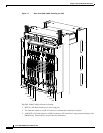
1.1 Installation Overview
The ONS 15600 is a Network Equipment Building System III (NEBS III)-compliant, environmentally
hardened shelf assembly that ships as a single shelf in a bay assembly for Release 7.2. The ONS 15600
comes with the power distribution unit (PDU), shelf, fans, and backplane already installed. The front