


1-11
Cisco ONS 15600 Reference Manual, R7.2
Chapter 1 Shelf and Backplane Hardware
1.7.2 Timing Installation
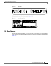
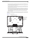
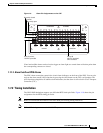
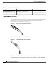
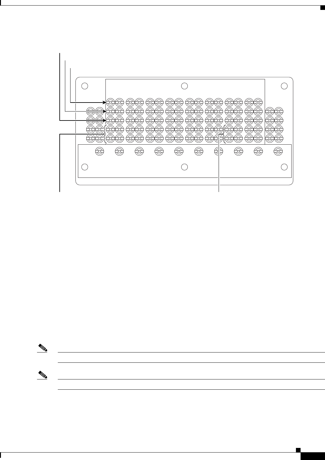
Figure 1-9 Alarm Pin Assignments on the CAP
Visual and audible alarms can be wired to trigger an alarm light at a central alarm collection point when
the corresponding contacts are closed.
1.7.1.2 Alarm Cutoff and PDU Alarms
The PDU Alarm connection controls the visual alarm indicators on the front of the PDU. You can also
activate the alarm cutoff (ACO) function by pressing the ACO button on the TSC card faceplate. The
ACO function extinguishes all audible alarm indications, but the alarm is still raised in Cisco Transport
Controller (CTC).
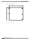
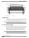
1.7.2 Timing Installation
The ONS 15600 backplane supports two 100-ohm BITS clock pin fields. Figure 1-10 shows the pin
assignments for the BITS timing pin fields.
Note
Refer to Telcordia SR-NWT-002224 for rules about provisioning timing references.
Note
64K and E1 timing are not used with SONET systems.
78510
16 15 14 13 12 11 10 9 87 65 43 21
BITS - B
BITS - A
EXTERNAL ALARMS
5
4
3
2
1
10 9 8 7 6 5 4 3 2 1
5
4
3
2
1
Normally open
Common
Normally closed
Short for alarm,
-48 VDC provided
Alarm IN
48 VDC provided
short contacts
FRAME GROUND