


6 7
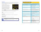
COMPONENTS AND CONNECTION
6
5 7
1
3
2
4
7
6 8
1
3
5
2
4
8
7 9
1
2
4
5
6
3
6 8
4
3
7
1
2
5
6 8
4
3
7
1
2
5
4
1 3
7 9
8
10
2
5 6
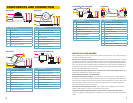
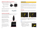
QD6001D QD6002D
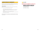
QD6003D QD6004B AND QD6501B
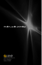
QD6005B AND QD6502B QD6503X
# Component
1 Clear Dome
2 Case
3 Base Release Screw (both sides)
4 Mounting Base
5 Multi-Function Button
6 Power Connector
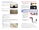
7 Video Connector (BNC)
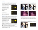
# Component
1 Optics (lens and IR LEDs)
2 Focus (behind rubber plug)
3 Body
4 Mounting Base
5 Zoom (behind rubber plug)
6 Multi-Function Button
7 Power Connector
8 Video Connector (BNC)
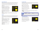
# Component
1 Optics (lens and IR LEDs)
2 Body
3 Base Release Screws (3)
4 Mounting Base
5 Zoom Knob (2.8mm - 12mm)
6 Focus Knob
7 Multi-Function Button
8 Power Connector
9 Video Connector (BNC)
# Component
1 Adjustable Sun Shade
2 Optics (lens and IR LEDs)
3 Zoom Knob (2.8mm - 12mm)
4 Focus Knob
5 3-Axis Mounting Bracket
6 Multi-Function Button
7 Power Connector
8 Video Connector (BNC)
# Component
1 Adjustable Sun Shade
2 Optics (lens and IR LEDs)
3 Zoom Knob (2.8mm - 12mm)
4 Focus Knob
5 3-Axis Mounting Bracket
6 Multi-Function Button
7 Power Connector
8 Video Connector (BNC)
# Component
1 CS Lens (packaged separately)
2 Lens Mount Spacing Adjustment
3 Auto Iris Port (on right side)
4 Focus Adjust
5 Iris Adjustment Ring
6 Zoom
7 Multi-Function Controls
8 Power Status Indicator
9 Power Connection
10 Video Connector (BNC)
INSTALLING YOUR CAMERA
When installing your camera, it is important to select a proper site not only for field of view, but
for other considerations as well:
Distance from viewing/recording device. The further the camera is from the DVR or monitor,
the higher the chances of signal degradation. Typical 75Ω Video Cable provides acceptable
signal at distances up to 200’ (30m). At greater distances, UL-Listed shielded RG59 should be
used. The camera’s power supply should be located as near to the camera as possible when
the distance exceeds 200’ as the power level will drop over extended distances resulting in a
decrease in video quality and IR LED range.
Do not place near high voltage wires or other sources of electrical interference. Electrical
interference will degrade the quality of the signal.
Place camera out of reach to avoid damage.
Avoid direct exposure to weather. Do not place the camera where rain or snow will hit the
lens directly nor should the camera be placed so that the sun or bright light shines directly into
the lens. Indoor cameras should never be placed outside. Weatherproof cameras will not work
when submerged. Ensure that all power and video connections are not directly exposed to
water and are protected from the elements.
Do not place camera behind a window. The IR LEDs act like a flashlight and will create a
reflection that will obscure events on the other side of the glass.
Light levels should be approximately the same between camera and target area. A
camera in a brightly-lit area looking into a shaded area, or vice versa, will produce inadequate
results.