


www.Fisher.com
D102796X012
FIELDVUE
R
HF300 Series HART
R
Filters
Introduction
Scope of Manual
This instruction manual includes installation and
maintenance information for the FIELDVUE
R
HF300
Series HART
R
Filters. Refer to separate manuals for
additional information on other FIELDVUE products
used with the HART filters, such as DVC6000 Series
digital valve controllers, and Type 2530H1 HART
interchange multiplexers.
Control system refers to a distributed control system
(DCS), programmable logic controller (PLC), or a
stand-alone controller that provides a control signal
to the FIELDVUE instrument.
Do not install, operate, or maintain HF300 Series
HART filters without first D being fully trained and
qualified in valve, actuator and accessory
installation, operation and maintenance and D
carefully reading and understanding the contents of
the manual. If you have any questions about these
instructions, contact your Emerson Process
Managementt sales office before proceeding.
Description
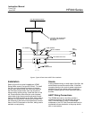
HF300 Series HART filters, shown in figure 1, are
used with HART-based FIELDVUE instrumentation,
such as DVC6000 Series digital valve controllers.
These filters are used when this instrumentation is
connected to a 4 to 20 mA DC control system output
that was not designed for the HART (Highway
Addressable Remote Transducer) communication
protocol.
The HF300 Series HART filters consist of the Type
HF340 HART filter that provides filtering and
isolation between the control system and FIELDVUE
instrument and the Type HF341 communication tap.
The Type HF341 does not provide any filtering. It is
simply a straight through device that provides a
convenient connection for HART communication.
FIELD INSTRUMENT CONNECTIONS (FLD)
HART COMMUNICATION
CONNECTIONS (COMM)
CONTROL SYSTEM
CONNECTIONS (SYS)
W8283 / IL
Figure 1. FIELDVUE
R
HF300 Series HART
R
Filters
The Type HF340 HART filter is a passive device that
is inserted in-line with both wires of a HART 4 to 20
mA DC output loop. The purpose of the filter is to
effectively isolate the control system analog output
from modulated HART communication signals. The
filter receives a 4 to 20 mA DC current signal from
the control system, which it shunts with a capacitor
and then passes through an inductor. The low AC
impedance of the capacitor prevents sudden
changes in the control system current output from
interfering with the HART communication. The high
AC impedance of the inductor permits HART
communication on the instrument side of the filter. It
also prevents the voltage modulation in the HART
loop from being seen by, or having an affect on, the
control system output. The filter introduces a
maximum input-to-output voltage drop of 2 volts DC
at 20 mA as long as the output load voltage is less
than 14 volts DC.
Instruction Manual
Form 5715
June 2007
HF300 Series