


HF300 Series
Instruction Manual
Form 5715
June 2007
3
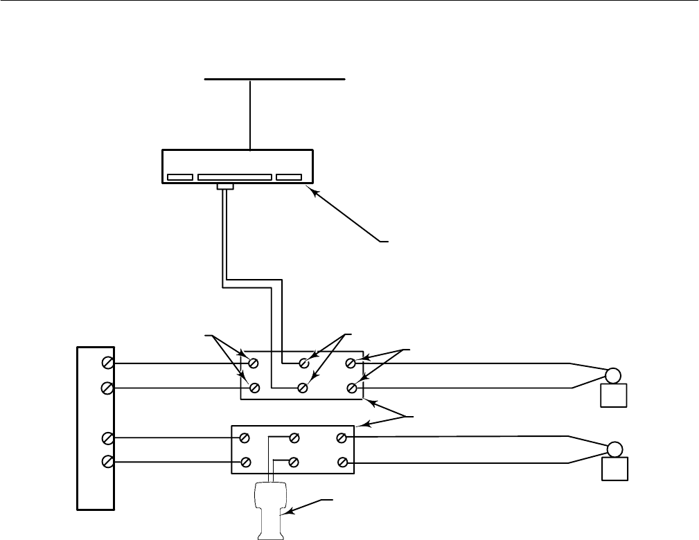
CONTROL
SYSTEM OUTPUT
TERMINALS
TYPE 2530H1 HART INTERCHANGE
MULTIPLEXER OR OTHER HART
MULTIPLEXER
FIELD
DEVICES
+
+
+
−
−
−
FLD TERMINALS
COMM TERMINALS
HF300 SERIES HART FILTER
+
+
−−
SYS TERMINALS
HART MULTIPLEXER NETWORK
375 FIELD
COMMUNICATOR
+
−
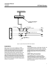
Figure 2. Typical HF300 Series HART Filter Installation
Installation
Refer to figure 2 for typical installations. HF300
Series filters mount on a type 35 DIN rail. To install
the filter, provide a temporary means of process
control, then take the loop out of service. Remove
the DIN interconnect blocks from the rail without
disconnecting existing wiring. Install the filter on the
rail. Disconnect the wires from the control system
output side of the interconnect blocks and connect
them to the SYS terminals on the filter, taking care to
maintain correct polarity. Disconnect the wires from
the field side of the interconnect blocks and connect
them to the FLD terminals on the filter, taking care to
maintain correct polarity.
Shields
If using shielded wiring on both sides of the filter, the
shield should connect across the filter. If the filter
connects directly to the control system output and
shielded loop wiring is being used, connect the
shield to system ground on the instrument side of
the filter.
HART Wiring Connections
The COMM terminals on the filter provide a
convenient means to tap into the loop wiring for
HART communication. A HART Interchange
multiplexer or the 375 Field Communicator can be
connected to these terminals, or they may be left
with no connections.