PRELIMINARY
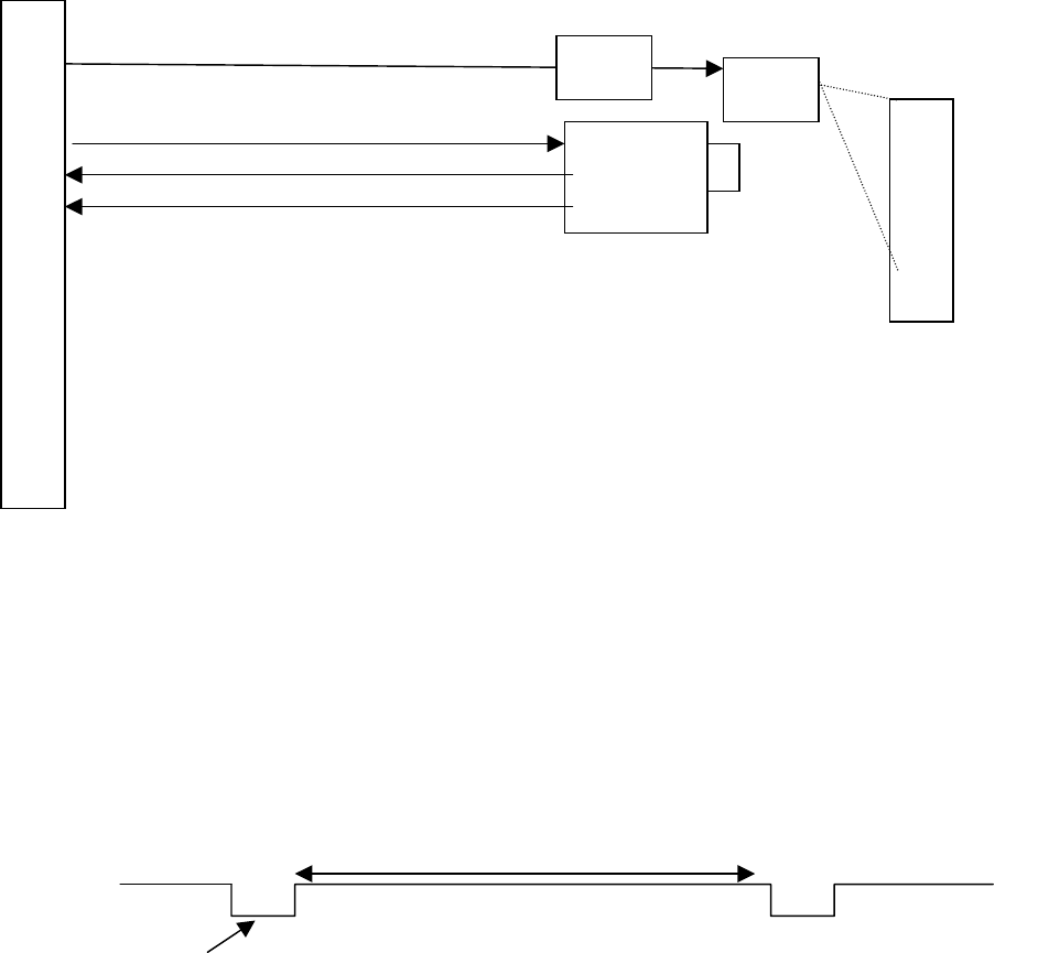
3.6 System Connection
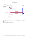
CAM
T
A
R
G
E
T
LED
Arra
y
LED TRIGGER (Inverted FRAME SEL)
LED
Dri
ver
VSYNC
HSYNC
FRAME SEL SIGNAL
F
R
A
M
E
G
R
A
B
B
E
R
VOLPI 18111.001
How to operate in framing mode
1. The camera must be running in master mode.
• External sync signal cannot be present at power up.
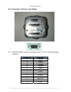
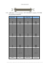
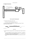
2. Provide a LVDS active low “FRAME SEL” LVDS signal to pin 5 and pin 13 of the
camera’s control connector (DB15).
READOUT TIME
EXPOSURE TIME
FRAME PULSE
1. Provide the LED with a trigger pulse that is active high during the camera’s exposure
time.
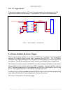
• An inverted FRAME SEL pulse with LED driver could be used. This requires a
LVDS receiver that will convert the FRAME SEL signal to TTL. This signal will turn
ON a transistor or a FET to drive the LED light source.
• If a TTL signal is available from the frame grabber, this could directly drive the LED
driver.
Fairchild Imaging • CAM/CCD-2KLV.TDI & CAM/CCD-4KLV.TDI Line Scan Camera User’s Manual • Rev 073004 • 22 of 38


