


© Copyright 2008 Fortinet Incorporated. All rights reserved.
Products mentioned in this document are trademarks or registered trade-
marks of their respective holders.
Regulatory Compliance
FCC Class A Part 15 CSA/CUS
28 March 2008
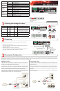
Checking the Package Contents
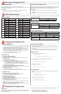
Connecting
Planning the Configuration
POWER
STATUS
Esc Enter
MGMT1
MGMT2
MODEM
CONSOLE
1
2
3 5 7 9 11 13 15
4
6 8 10 12 14 16
ASM
Straight-through Ethernet for access
to the web-based manager
Optional RJ-45 to DB-9 cable connects
to serial port on management computer
Power cables connect
to power outlets
Fiber optic cable
connects
to internal network or Internet
POWER
STATUS
Esc Enter
MGMT1
MGMT2
MODEM
CONSOLE
1
2
3 5 7 9 11 13 15
4
6 8 10 12 14 16
ASM
Power alarm reset button
Inte rnet
Router
Internal
network
Port 3
10.10.10.1
10.10.10.2
Internal Network
192.168.1.3
Port 2
192.168.1.99
Routing policies controlling
traffic between internal
networks.
Port 1
204.23.1.5
NAT mode policies controlling
traffic between internal
and external networks.
Internet
Router
DMZ net
w
ork
Web Server
Mail Server
Internal
network
Hub or switch
Port 3
Poirt 1
Port 2
Back
Front
Power
Connections
Power Cables (2)
Rack-Mount Brackets
Documentation
Ethernet Cables:
Orange - Crossover
Grey - Straight-through
USER MANUAL
RJ-45 to
DB-9 Serial Cable
FortiG ate-3016B
Copyright 2007 Fortin et Incorpor ated. All r ights reser ved.
Trademarks
Products mentioned in this docum ent are tra demarks.
Q ui ck S ta rt G ui de
POWER
STATUS
Esc Enter
MODEM
CONSOLE
1 357 911131517
4
681012141618
FG-AMC-SW
4x Optical Transceivers
4x Copper Transceivers
POWER
STATUS
Esc Enter
MGMT1
MGMT2
MODEM
CONSOLE
1
2
3 5 7 9 11 13 15
4
6 8 10 12 14 16
ASM
Copper
Management
Ports
Fiber Ports
USB
Serial and
Modem Connections
LCD Display
Control Buttons
Connect the FortiGate unit to a power outlet and to the internal and external networks.
Place the unit on a stable surface.
Connect both power cables into the back of the FortiGate unit, then plug the power
cables into a power bar.
MAIN MENU appears when the unit is up and running.
If only one power supply is connected, an audible alarm sounds to indicate a failed
power supply. To stop this alarm, press the red alarm cancel button.
•
•
•
•
Before beginning to congure the FortiGate unit, you need to plan how to integrate the unit into your network. Your conguration plan is dependent upon the operating mode that you select:
NAT/Route mode (the default) or Transparent mode. Refer to the Documentation CD-ROM for information on how to control trafc, and how to congure HA, antivirus protection, FortiGuard,
Web content ltering, Spam ltering, intrusion prevention (IPS), and virtual private networking (VPN).
NAT/Route mode
In NAT/Route mode, each FortiGate unit is visible to the network that it is connected to. All
of its interfaces are on different subnets. Each interface connected to a network must be
congured with an IP address that is valid for that network.
You would typically use NAT/Route mode when the FortiGate unit is deployed as a gateway
between private and public networks. In its default NAT/Route mode conguration, the unit
functions as a rewall. Firewall policies control communications through the FortiGate unit.
No trafc can pass through the FortiGate unit until you add rewall policies.
In NAT/Route mode, rewall policies can operate in NAT mode or in Route mode. In NAT
mode, the FortiGate unit performs network address translation before IP packets are sent to
the destination network. In Route mode, no translation takes place.
Transparent mode
In Transparent mode, the FortiGate unit is invisible to the network. All of its interfaces are on
the same subnet. You only have to congure a management IP address so that you can make
conguration changes.
You would typically use the FortiGate unit in Transparent mode on a private network behind
an existing rewall or behind a router. In its default Transparent mode conguration, the unit
functions as a rewall. No trafc can pass through the FortiGate unit until you add re-
wall policies.
You can connect up to four network segments to the FortiGate unit to control trafc between
these network segments.
FortiGate-3016B
01-30006-0402-20080328
LED State Description
Power
Green The FortiGate unit is on.
Off The FortiGate unit is off.
Status
Green The FortiGate unit is running normally.
Off The FortiGate unit is off.
MGMT1 and
MGMT2
(Right LED)
Green The correct cable is in use and the connected equipment
has power.
Flashing Green Network activity at this interface.
Off No link established.
MGMT1 and
MGMT2
(Left LED)
Green Connection at 1000 Mb.
Amber Connection at 100 Mb.
Off Connection at 10 Mb.
Ports 1 to 16
Green The correct cable is in use and the connected equipment
has power.
Flashing Green Network activity at this interface.
Connector Type Speed Protocol Description
MGMT1 and
MGMT2
RJ-45 10/100/1000
Base-T
Ethernet Copper gigabit connection to 10/100/1000
copper networks.
Ports 1 to 16 LC SFP 1000Base-SX Ethernet Multimode ber optic connections to
gigabit optical networks for small packet
performance required for voice, video and
other multimedia streaming applications.
CONSOLE RJ-45 9600 bps
8/N/1
RS-232
serial
Optional connection to the management
computer. Provides access to the com-
mand line interface (CLI).
USB USB USB Optional connection to a USB key for
rmware backup and installation.