


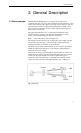
3. Installation
3.5 Installation of
the flow cell
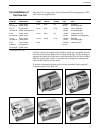
Monitor UV-1 accepts flow cells for Standard Chromatography, FPLC
and industrial applications.
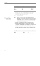
Product Material of Path Total dead IlluminatedPressure Application
Code No. wetted parts length volume volume limit area
S-2 Fluoro-plastic, 2 mm 80 µl 2 µl 0.3 MPa Standard
19-4840-02 optical quartz (3 bar) Chromatography
HR-10 Fluoro-plastic, 10 mm 24 µl 8.7 µl 1.0 Mpa FPLC, Standard
19-6254-02 optical quartz,titanium (10 bar) Chromatography
3 mm Fluoro-plastic, 3 mm 50 µl 3 µl 1.0 MPa Preparative FPLC,
19-2503-02 optical quartz (10 bar) Standard Chromatography
10 mm Fluoro-plastic, 10 mm 250 µl 8.7 µl 1.0 MPa Standard
19-2504-02 optical quartz (10 bar) Chromatography
5 mm Silicon rubber, 5 mm 0.2 MPa* Industrial scale
Industrial polypropylene, (2 bar)
19-4510-02 optical quartz
* Flow rate 300 I/h at 0.1 MPa
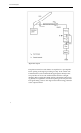
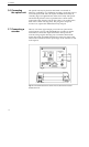
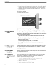
All flow cell are mounted in the holders, ready to be installed directly
into the cell housing. Release the locking knob (Fig. 4:6) by turning it
against the direction of the arrow and insert the flow cell in its holder
into the optical unit. Lock it in position by turning the locking knob
fully in the direction of the arrow.
For more information please refer to the instruction sheet supplied
with the respectively flow cell.
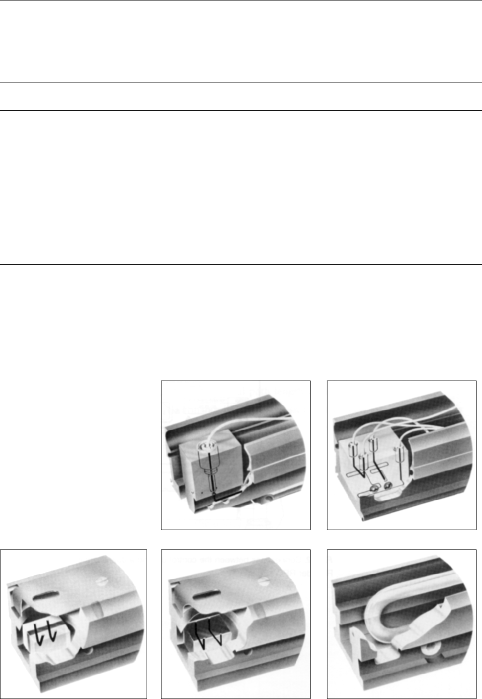
Fig. 7.
S-2 flow cell
Fig. 8.
HR-10 flow cell
Fig. 9.
3 mm flow cell
Fig. 10.
10 mm flow cell
Fig. 11.
Industrial flow cell
13