


20
Installation and Setup
the client (PC) and provide an industry standard line level output suitable to connect to
audio devices. Audio input and output have 600 Ohm impedance. See Audio Settings on
page 63 to configure audio options.
Connecting Alarms
WARNING! Do not exceed the maximum rating of 12 VDC, 0.5 A on alarm
output connections.
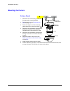
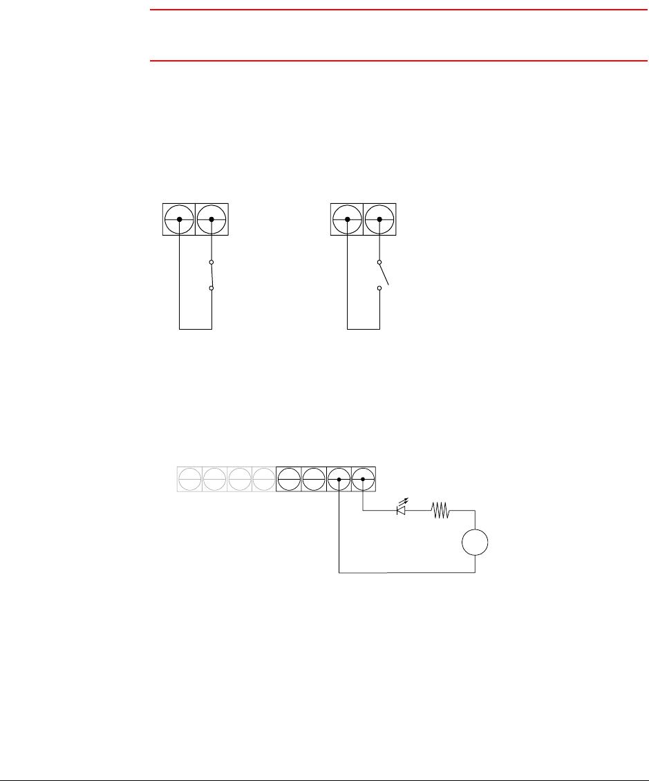
The HD3MDIP/X network camera has one alarm input and one alarm output. Connect
mechanical or electrical switches to the alarm input connection to allow event-triggered
recording. When alarm inputs are configured, the HD3MDIP/X triggers an alarm only when
the normal alarm state (open or closed) changes.
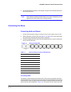
Figure 2-4 Normal Alarm States
See Alarm Settings on page 62 to configure the alarm inputs.
Connect external devices such as sirens or flashing lights to the alarm output connector to
signal an activated alarm to camera users.
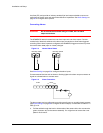
Figure 2-5 Alarm Connection
The alarm output can be configured to provide normally open or normally closed contacts
(see Alarm Settings on page 62 to configure the alarm output). Contacts will be rated for 12
VDC @ 0.5 A.
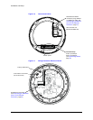
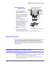
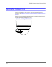
4. Pull the cables through the back or side entries of the camera skirt, then connect the
green connector strip to the camera assembly. You might have to remove the cover
plate for flush mount.
Normally closed
Normally opened
In
Audio
Alarm
Out
+−
+
−