


HD3MDIP/X Network Camera Reference Guide
Document 800-04132V1 Rev A 25
01/10
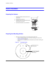
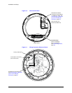
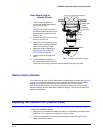
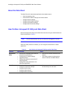
Flush Mount (with or
without 4S box)
1. Use the screws (supplied) to
connect the adapter plate directly
to the ceiling or wall.
Or
Use your own screws to connect
the adapter plate to the 4S box (not
supplied) which is attached to the
ceiling or wall.
2. Connect the wires (see Connecting
the Wires on page 19).
3. Secure the camera assembly to the
adapter plate by twisting clockwise
until it clicks securely in place.
4. Adjust the camera’s field of view
(see Adjusting the Camera FOV
(Field of View) on page 25).
5. Install the turret by clicking it into
place.
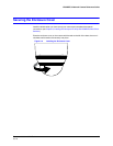
6. Install the bubble by placing it on
the camera with the tabs to the left
of the slots, then turning it clockwise until the tabs click securely into place.
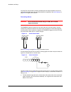
Restore Factory Defaults
Your network camera has a Factory Reset switch located inside the camera (see Figure 2-6
on page 22). This switch restores your camera settings and passwords to their default
settings. Press and hold the Reset switch for three seconds. This will reset the
factory-configured parameters such as the compression settings, the camera tamper
detection settings, and the Video Motion Detection settings. It will not impact network IP
address configurations.
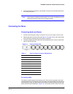
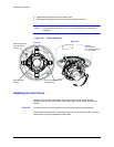
Adjusting the Camera FOV (Field of View)
To adjust the HD3MDIP/X camera:
1. Apply power to the camera and watch the video on a connected local video monitor
(see Figure 2-7 on page 22 to connect a local video monitor).
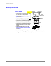
2. Loosen the setscrew that locks the gimbal assembly in place (see Figure 2-8) to
adjust the horizontal rotation.
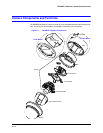
Bubble
Adapter plate
Camera
assembly
Turret
Note Installation with 4S box shown
4S box (not supplied and optional)
Screws
(supplied)
Screw caps