


HD3MDIP/X Network Camera Reference Guide
Document 800-04132V1 Rev A 19
01/10
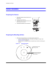
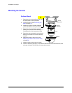
2. Pre-drill the holes as indicated on the template, using the recommended hole size for
the screws being used.
Note Other fasteners (preferably stainless steel) can be used, provided they are not
larger than the screw holes on the mounting template.
Connecting the Wires
Connecting Audio and Alarms
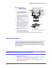
1. Pull the wires through the ceiling or wall hole until you have at least 4 inches of wire.
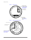
2. Remove the green connector strip (see Figure 2-6 on page 22) from the camera base
and make all the necessary alarm and audio connections.
3. Connect a twisted pair (UTP) cable from each peripheral alarm contact to each alarm
input on the terminal block.
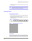
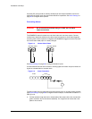
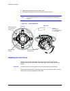
Figure 2-3 Audio and Alarm PINs
Connecting Audio
The network camera supports bi-directional audio. There are two supported voice band
channels that function in full duplex mode. The camera can transmit audio from the camera
to the client (PC) using any audio source that provides an industry standard line level input
(see the terminal strip as depicted in Figure 2-6). The camera can also receive audio from
1
2
34
5
6
7
8
Power
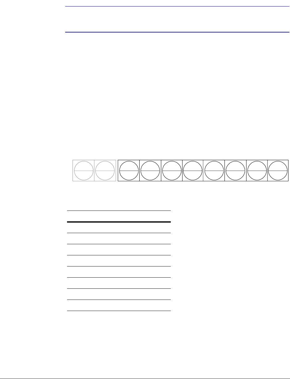
Table 2-1 Audio and Alarm Connector PIN Definitions
PIN Definition
1 Audio In +
2 Audio In -
3 Audio Out +
4 Audio Out -
5Alarm In +
6Alarm In -
7Alarm Out +
8Alarm Out -