1. Features
NIGHT VISION IR DOME CAMERA
2
2. Safety Precautions
NIGHT VISION IR DOME CAMERA
3. Handling of the Unit
3
NIGHT VISION IR DOME CAMERA
4
NIGHT VISION IR DOME CAMERA
5
NIGHT VISION IR DOME CAMERA
6
IR NIGHT VISION DOME CAMERA
7
NIGHT VISION IR DOME CAMERA
1
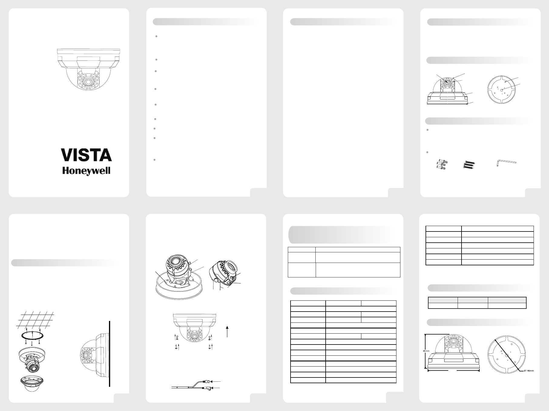
10. Dimension Outline
NIGHT VISION IR DOME CAMERA
User Guide
VDC-350PIV-V
The camera adopts advanced Digital Signal
Processor(DSP) technology,Enhances picture
quality greatly to horizontal resolution of
540TVL. Provides clearer and more vivid image.
capture high-resolution picture even in complete
darkness. Night view distance up to10~15m.
Integrated efficient powerful IR LED array can
Light control design. Auto light detection for IR
LED switch control.
The camera is equipped with a Vari-focal lens,
f=4~9mm.
Accept 12VDC power supply.
Latest DSP controls for BLC, white balance,
and gain control.
The installation should be made by qualified service
personnel or system installers and should confirm
to all local codes.
1.Power supply
(1) use with a 12VDC regulated power supply
(2) To prevent fire or electrical shock, UL listed class
2 wiring should be used for the 12VDC input terminal.
(3) Be used to connect each lead to the appropriate
terminal. Wrong connection may cause malfunction
and/or damage to the video camera.
2.Operating and storage locations
(1).Do not attempt to point the camera at the sun or
other extremely bright objects that cause smear to
appear no matter the camera is power on or not.
It leads to damage of the CCD(Charge Coupled
Device).
(2).When camera is installed next to equipment,
such as wireless communication device, it emits a
strong electromagnetic field, some irregularity such
as noise on the monitor screen may happen.
(3).Be sure to use a ceiling board having enough
strength to support this camera.
(4).Assemble the camera's main parts and lens
quickly in a sanitary place.
(5).Do not pull the cable, it may cause disconnection.
(6).Do not touch the inside of camera even if
something is wrong.
(7).Before installation, make sure to disconnect the
power supply first, check the ground connection,
and then install it.
(8).Operating temperature range:-10℃~+50℃,(14°F~122°F);
Storage temperature range:-20℃~+60℃,(-4°F~140°F).
(9). Be sure to use proper screws which cameras can
be beared on the material firmly.
(1) Never attempt to disassemble or modify the camera.
(2) If an abnormality should occur, immediately turn off
the power and consult your dealer.
6. Installation
4. Adjusting the Camera Direction
Camera body moves in three ways: pan, tilt and rotate.
Adjust the direction so that the lens is pointing at the
target.
5. Use the lever to adjust the view angle and focus.
8. Specifications
All data and specifications subject to change
without notice.
9. Type Number Overview
Model(12VDC)
Signal system
PAL
VDC-350PIV-V
NTSC
VDC-350NIV-V
Manual pan /tilt mechanism,3-Axis Rotation.
Anda polygon dome shield, which can bear up to
120 pounds impact and won't be destroyed. It
has excellent sealing performance and can also
be installed by outdoor .
Polygon material made dome shield possesses
high light permeate rate, strong shock resistance
capability. The whole Aluminum base can stand
lasting shock and high temperature.
4. Parts Description
Front View
Body cover
Dome cover (transparent)
Camera body
Camera base
IR-LED
BOTTOM View
Mounting Holes
Wire hole
5. Cover Removal and Attachment
To remove the body cover and camera body,
disassemble it with the L WRENCH provided in your
ACCESSORY set. (Rotating clockwise will close it
and rotating anti-clockwise will release it.)
Acecessories
3. L WRENCH
1. PLASTIC
ANCHOR
2. ASSY SCREW
TAPPING
1.PLASTIC ANCHOR: insert into the SCREW hole of the
installation location(to strengthen the installation).
2.ASSY SCREW TAPPING:use for installation on the
ceiling or wall.
3. L WRENCH:for body cover and camera base
assembly.
1.Drill a hole in the place where the camera is
installed. Completely insert the PLASTIC ANCHOR
provided. then lead the power and video cables pass
through the hole.
2.Disassemble the body cover and camera base
from dome camera .
3.Fasten the dome camera base on the wall or the
ceiling.
Ceiling
Wall
Pan360°
Tilt 90°
Rotate 180°
View angle
adjustment lever
Focus
adjustment lever
6 urn the dome cover to adjust until the lens point at T
the window, screw tightly and complete the installation.
.
Close
7. Connecting Low Voltage Power & Video Signal
The wiring harness have a BNC connector to accept
video signal ,the other connectors to accept the low
voltage power. For mounting directly to a wall or ceiling,
run power and video lines to the target location.
12VDC
VIDEO
NIGHT VISION IR DOME CAMERA
7. Self-Check Points
Before Consulting After-Sales Services
Screen
not turned on
*Make sure whether power is connected correctly.
*Check if the cable is connected correctly.
Screen not clear
or is spread
*If dust is seen through the monitor screen after
fixing lens, dissemble the lens and clear off the
dust on the surface of CCD withblower or soft cloth.
CONDITIONS
CHECKING POINTS
146mm
VDC-350NIV-V
Model VDC-350PIV-V VDC-350NIV-V
Image Sensor
Signal System PAL NTSC
Effective Pixels 752(H)x582(V) 768(H)x494(V)
Resolution
Minimum Illumination
Shutter Speed 1/50-1/100,000SEC 1/60-1/100,000SEC
S/N Ratio
White Balance
AGC/BLC
Gamma Correction
Sync Model
Lens
IR LED
IR Beam Distance
More Than 50dB
1/3'' SUPER HAD II CCD
0.1Lux/F1.2(IR LED OFF), 0Lux (IR LED On)
540TV Lines(Color), 600TV Lines(B/W)
Automatic
Automatic
0.45
INT
Varifocal lens, f=4-9mm
Wave Length 850nm, x 21pcs IR LED
10~15m
6
IR LED Drive
Video output
Power Input
Power Consumption
Operating Temperature
Body
Weight
On: 1~3Lux; Off: 5~6Lux
1.0Vp-p, 75Omh, Sync Negative Polarity
1000g
DC12V Regulated
150mA(IR LED OFF)+150mA(IR LED ON)
-10℃ ~ +50℃, RH90% MAX (non-condensing)
Aluminum