


Installing options 43
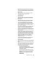
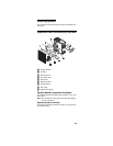
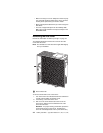
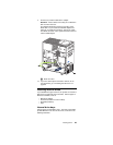
1 Switch block
2 Flash ROM page swap jumper (J38)
System board jumper blocks
Any jumper blocks on the system board that are not shown
in the illustration are reserved. For normal operation of the
system, no jumpers should be installed on any of the jumper
blocks except the J38 Flash ROM page swap jumper. See
“Recovering BIOS” on page 13 for information about the
Flash ROM page-swap jumper.
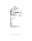
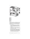
System board switch block
The switch block contains microswitches 1-8. As pictured in
this illustration, switch 8 is at the right of the switch block and
switch 1 is at the left.
The following table describes the function for each switch.
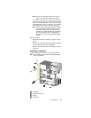
Before you begin
Before you begin to install options in the server, become
familiar with the safety and handling guidelines provided in:
• “Safety information” on page 155;
• “Handling electrostatic discharge-sensitive devices” on
page 158; and
• “Safety notices (multi-lingual translations)” on page
159.
These guidelines will help you work safely while working
with the server or options.
• The blue color on components and labels identifies
touch points where you can grip a component, move a
latch, and so on.
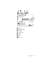
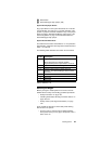
Switch
number
Switch
description
8 Bypass power-on password.
When toggled to the opposite position,
bypasses the power-on password, if one is set.
7 Reserved. The default setting is Off.
6 Reserved. The default setting is Off.
5 Forces system power on when set to On
position. The default setting is Off for normal
operation.
4 Reserved.
3 Reserved.
2 Reserved.
1 Reserved.
Table 6. Switches 1-8