


9
I
I
n
n
s
s
t
t
a
a
l
l
l
l
i
i
n
n
g
g
t
t
h
h
e
e
P
P
o
o
r
r
t
t
c
c
o
o
n
n
t
t
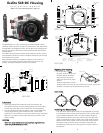
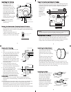
To prepare the port for installation remove the port o’ring and
lightly lubricate it The port seal is a sidetoside seal and
requires the o’ring to be lightly lubricated for easy installation
Put a small amount of lubricant on your fingers and draw the
o’ring through your fingers to lightly lubricate it Do not stretch
the o’ring Check that the lip of the port where the o’ring fits
a
nd the sealing surface on the housing are clean Place the port
with o’ring into the housing’s port opening Press down on the
p
ort firmly and evenly until you feel the port slide into place
Continue to push down on the port and push each port lock
f
orward until it clicks into place It may help to slightly rotate
the port as you push in on the port lock When the port lock
clicks into place the Release Button will drop down against the
port lock
C
heck around the perimeter of the port seal to see that the
o’ring is properly sealed and not extruded
T
T
o
o
R
R
e
e
m
m
o
o
v
v
e
e
P
P
o
o
r
r
t
t
To remove the port lift up on each Release Button and slide the
port lock away from the port
P
P
o
o
r
r
t
t
S
S
e
e
a
a
l
l
I
I
n
n
s
s
i
i
d
d
e
e
V
V
i
i
e
e
w
w
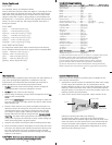
If the port is installed before the
camera is inserted into the housing
look on the inside of the housings at
the port seal Check to see that the
o’ring is properly sealed as shown in
figure and not extruded as shown in
figure
Fig
Fig
10
U
U
s
s
i
i
n
n
g
g
E
E
x
x
t
t
e
e
r
r
n
n
a
a
l
l
S
S
t
t
r
r
o
o
b
b
e
e
s
s
T
his housing has Conversion Circuitry built into the camera
tray When used with Ikelite DS Substrobes the Conversion
C
ircuitry provides real Canon eTTL flash exposure with over and
underexposure compensation of two fstops in halfstop
i
ncrements
The Consversion Circuitry also offers Manual exposure control
with / fstops of underexposure control in / stop
increments
The Conversion Circuitry is powered by the Ikelite DS Substrobe
when connected to the housing with the single or
dual sync cord
See page for DS Substrobe compatibility with the Conversion
Circuitry
12
N
N
O
O
T
T
E
E
:
:
D
D
S
S
S
S
u
u
b
b
s
s
t
t
r
r
o
o
b
b
e
e
U
U
p
p
d
d
a
a
t
t
e
e
m
m
a
a
y
y
b
b
e
e
r
r
e
e
q
q
u
u
i
i
r
r
e
e
d
d
D
D
S
S
S
S
u
u
b
b
s
s
t
t
r
r
o
o
b
b
e
e
s
s
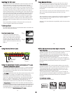
• DS SubStrobes with a Serial Number below can not be
updated to operate with the eTTL Conversion Circuitry
• DS SubStrobes with a Serial Number between and
operate with the eTTL Conversion Circuitry but require
update to provide optimum performance
• DS Substrobe with a Serial Number of or higher or
with one of the two following labels in the battery compartment
provide optimum performance with the eTTL Conversion
Circuitry
D
D
S
S
S
S
u
u
b
b
s
s
t
t
r
r
o
o
b
b
e
e
s
s
• DS Substrobes with a Serial Number below must be
updated to operate correctly with the eTTL Conversion Circuitry
• DS Substrobes with a Serial Number between and
operate with the eTTL Conversion Circuitry but require
update to provide optimum performance
• DS Substrobe with a Serial Number of or higher or
with one of the two following labels in the battery compartment
provide optimum performance with the eTTL Conversion
Circuitry
ikelite
SubstrobeSubstrobe
MOD-NC
serial number
serial number
F
F
o
o
r
r
S
S
u
u
b
b
s
s
t
t
r
r
o
o
b
b
e
e
U
U
p
p
D
D
a
a
t
t
e
e
:
:
Contact Ikelite for information
11
U
U
s
s
i
i
n
n
g
g
t
t
h
h
e
e
C
C
o
o
n
n
v
v
e
e
r
r
s
s
i
i
o
o
n
n
C
C
i
i
r
r
c
c
u
u
i
i
t
t
r
r
y
y
((SSeett DDSS SSuubbssttrrbbooee ttoo TTTTLL mmooddee))
•
•
M
M
o
o
d
d
e
e
a
a
n
n
d
d
C
C
o
o
m
m
p
p
e
e
n
n
s
s
a
a
t
t
i
i
o
o
n
n
B
B
u
u
t
t
t
t
o
o
n
n
s
s
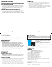
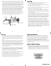
The Conversion Circuitry default is set to TTL To switch between
TTL and Manual Modes depress both Mode Buttons at the same
time and keep then depressed until you see the desired Yellow
LED Mode illuminate
•
•
T
T
T
T
L
L
M
M
o
o
d
d
e
e
(indicated when the Yellow LED directly below TTL is
illuminated) TTL Mode is the default setting When the DS
Substrobe is powered ON the Yellow TTL LED will illuminate
None of the Red LEDs will illuminate This indicates that NO ()
plus or () minus compensation is selected Depress the Mode
buttons to select / compensation Note that the TTL /
compensation values are in the yellow bar with the heading TTL
•
•
M
M
a
a
n
n
u
u
a
a
l
l
M
M
o
o
d
d
e
e
(indicated when the Yellow LED directly below
the M is illuminated) When the Manual Mode is selected the Red
LED directly below the F (full power) will illuminate Note that
the Manual minus () compensation values are in the black bar
with the heading M
((SSeett DDSS SSuubbssttrrbbooee ttoo TTTTLL mmooddee))
F
-1-2-3
M
••••
MODE
-2
-1 +1 +2
TTL
••••
Red LEDs (Compensation)
Mode &
Compensation
Buttons
Manual Mode
Yellow LED
TTL Mode
Yellow LED
33
U
U
s
s
i
i
n
n
g
g
E
E
x
x
t
t
e
e
r
r
n
n
a
a
l
l
S
S
t
t
r
r
o
o
b
b
e
e
s
s
C
C
o
o
n
n
t
t