


Congratulations on your purchase of an Ikelite Digital Camera
Housing. Ikelite has over 40 years of experience in the underwater
photographic and lighting market. Our products are designed and
built in the USA by Ikelite for both the professional and amateur
photographer.
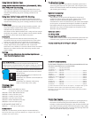
The clear housing permits instant visual inspection of the camera
and all sealing surfaces as well as complete monitoring of controls
and camera LCD screens.
Ikelite Digital Housings are slightly negative in salt water for
stability. This housing has been water pressure tested at the
factory. Housing is pressure tested to 200’ (60m).
Ikelite SLR-DC Housing
i n s t r u c t i o n m a n u a l
#6812 for Nikon D200
3
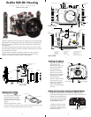
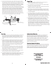
SIDE VIEW
Camera
Tray
Camera
Mounting
Bolt
Gear
Sleeve
Port
O'ring
Port Lock
Optional
Port
Lid
Snap
Shutter
Release
AE Lock
Back O’ring
Sub-command
Dial
DOF-FUNC
Format/Exposure Comp.
Power
OOppeenniinngg tthhee HHoouussiinngg
1. Lid Snaps have a
LLoocckk
.
To open, push Lid Snap Lock
forward and lift as shown.
Keep pressure on the Lid
Snap so it does not fly open
quickly.
Some lid snaps have a lot of
spring tension once they go over center, have a firm grip on the
lid snap. Lid Snaps may be opened one at a time.
Lift
Push Forward
Lid Snap Lock
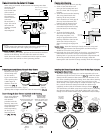
2
S
trobe
M
ount
Rubber
H
andle
Q
uick-Release
S
trobe
M
ount
Gear Sleeve
Drive Gear
Zoom
Control
L
id Snap
Sub-Command
Dial
L
ens
R
elease
Focus Mode
Power
F
ormat/Exposure Comp.
Flash
Lid
Snap
S
hutter
R
elease
Port Lock
Aluminum Tray
P
ort
O
pening
DOF-FUNC
Q
uick
R
elease
B
utton
E
xternal Strobe Connector
a
nd Waterproof Cap
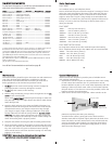
Viewfinder Po rt
[
E] Thumbnail
[
F] Protect
[
G] Enter
[
H] AF-ON
[
I] Main Command Dial
[
J] Multi-Selector
[
K] AF-area
[
L] Card Cover Latch
[
M] Flash Compensation
AB
C
D
E
F
G
H
K
L
M
I
J
Lens
Release
Zoom
AE-AF Lock
QUAL
White Balance
ISO
[
A] Bracket
[
B] Delete
[
C] Playback
[
D] Menu
T
TL
1
-1
-1
F
-2
-3
MAN
FRONT VIEW
BACK VIEW
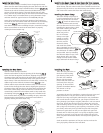
IInnssttaalllliinngg tthhee CCaammeerraa
Remove the back from
the housing. The
mounting tray for the
camera is secured to
the housing back.
Position the camera
with lens on the tray
and secure it with the
mounting bolt which
threads into the
camera’s tripod socket.
Use a tool or coin to
tighten the mounting
bolt so the camera
bottom is flush against
the tray.
Camera Tray
O‘ring
Mounting Bolt
4
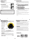
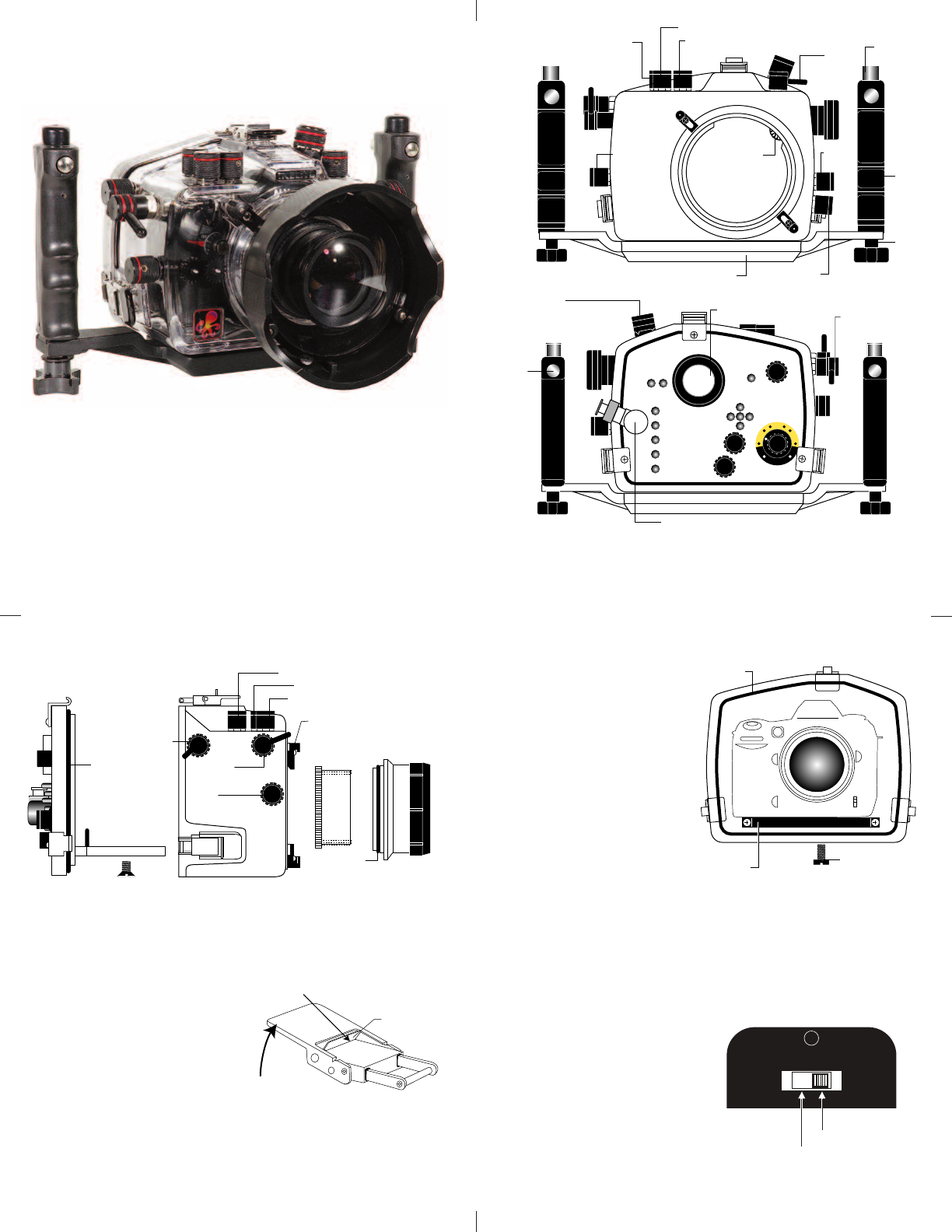
SSeettttiinngg tthhee CCoonnvveerrssiioonn CCiirrccuuiittrryy SSttrroobbee IIDD SSwwiittcchh..
Inside the housing back on the black panel housing (see
illustration next page) the conversion circuitry is a switch for
setting the DS Substrobe ID.
Set the switch to the Model
of DS Substrobe being used,
SD125/DS200 or DS51.
• When using dual strobes
of different models such as
a DS51 and a DS125, set the
ID switch to DS51.
DS DS
125 50/51
200 80
++
DS125 / DS200
DS50 / DS51 / DS80