


5
F
F
l
l
a
a
s
s
h
h
C
C
o
o
n
n
n
n
e
e
c
c
t
t
i
i
o
o
n
n
f
f
o
o
r
r
E
E
x
x
t
t
e
e
r
r
n
n
a
a
l
l
S
S
t
t
r
r
o
o
b
b
e
e
s
s
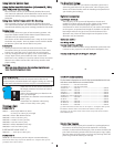
When using an external strobe connect the housings Hot Shoe
Connector, slide
the connector
into the hot shoe
of the camera
f
rom the back of
the camera as
shown. Slide the
connector
f
orward until it
stops. This can be
done after the
camera is secured
with the
mounting bolt.
External Strobe Connector
W
aterproof Cap
O
'ring
Strobe ID
S
witch
Housing Back
H
ot Shoe
C
onnector
Camera
C
C
a
a
u
u
t
t
i
i
o
o
n
n
:
:
Do not remove the External Strobe Connector’s waterproof cap
unless an external sync cord is going to be plugged in.
I
I
n
n
s
s
t
t
a
a
l
l
l
l
i
i
n
n
g
g
C
C
a
a
m
m
e
e
r
r
a
a
i
i
n
n
H
H
o
o
u
u
s
s
i
i
n
n
g
g
Before installing the camera, pull out on the controls in the front
section of the housing. This will allow the camera to slide in
easier. Once the camera is installed and the lid snaps have been
closed, return the controls to their operating position.
6
C
C
l
l
o
o
s
s
i
i
n
n
g
g
t
t
h
h
e
e
H
H
o
o
u
u
s
s
i
i
n
n
g
g
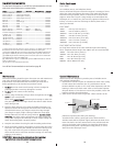
1. Place housing face down in your lap.
2. Check to see that there is an
o’ring on the housing back and
that it is clean and in its proper
location.
3. Guide the back onto the housing.
The o’ring should touch the
housing all the way around.
There should be an even gap all
the way around between the
housing and the housing back.
4. Lift the lid snaps so they are
extended and place the lid snap
into the hook on the housing
b
ack.
5. To close the housing push
down on the lid snaps until
they snap into place . Lid
snaps on opposite sides of the
housing should be closed at the
same time. Be sure they are
down far enough to engage the
lock.
DDoouubbllee cchheecckk
- Once the housing is closed, check the o’ring seal.
Check the gap between the housing back and the housing, it
should be even all the way around.
Look through the clear plastic back at the o’ring. You should see a
darkened area where the o’ring is compressed against the
housing back. If you do not see an even black compression seal
all the way around the back, open the lid snaps, reseat the
housing back and close the lid snaps. Visually check the seal again.
o’ring
housing back
housing back
housing
housing
o’ring
even gap
all 4 sides
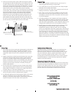
IInnssttaalllliinngg tthhee ZZoooomm CCllaammpp && GGeeaarr SSlleeeevvee OOnn tthhee TTyyppee 11 LLeennsseess
IInnssttaalllliinngg tthhee ZZoooomm CCllaammpp
The Zoom Clamp has springs so it can be expanded to fit over
the Zoom ring of the lens as shown in
((FFiigg.. CC))
. Install the Zoom
Clamp with the extension tabs toward the rear element of the
lens. After installing the Zoom Clamp, check that when rotating
the Zoom Clamp it rotates the Zoom ring on the lens. If the
Zoom Clamp is not tight enough to rotate the Zoom ring on the
lens, remove the Zoom Clamp and install the rubber strips
(supplied) to the inside of the Zoom Clamp as shown
((FFiigg.. FF))
.
Two thicknesses of rubber strips are provided. Start by installing
the thinnest rubber strips, if the Zoom Clamp still is not tight
enough use the thicker rubber strips. Reinstall the Zoom Clamp.
Type 1 Installation: Figure A
Figure A
Type 1 Installation: Figure B
Figure B
Type 1 Installation: Figure C
Figure C
Figure C Figure D Figure E
Type 1 lens
mounted
to camera
gear sleeve
ribs
align with
groove in
zoom clamp
extension
tab
mesh
gear sleeve ribs
with black housing
drive gear
apply
rubber strips
to inside of
clamp
zoom
ring
Figure F
8
PPrreeppaarriinngg ttoo IInnssttaallll ZZoooomm CCllaammpp && GGeeaarr SSlleeeevvee
Determine the type
of lens being used
on the camera.
Type 1 Lenses have
a lens opening that
is NOT larger in
diameter than the
zoom ring.
((FFiigg.. 11))
.
Type 2 Lenses have a lens
opening that IS larger in diameter than the zoom ring.
((FFiigg.. 22))
.
ZZoooomm CCllaammppss && GGeeaarr SSlleeeevveess IInncclluuddeedd wwiitthh HHoouussiinngg
There are 2 different
Zoom Clamps and
Gear Sleeves
provided with the
housing. Start with
the suggested Zoom
Clamp and Gear
Sleeve depending
on the Type of
lens being used.
See
((FFiigg.. AA oorr BB))
Figure B-Type 2 Lens
Figure A-Type 1 Lens
lens
opening
zoom
ring
bayonet
mount
Type 1 lens Type 2 lens
(Figure 1) (Figure 2)
Figure G
Normally used with
Type 1 lens (Fig.1)
#9059.8 small diameter clamp:
For use with #0073 sleeve
+
#0073 sleeve: Use with
small diameter zoom clamp
#9059.8
Figure A
Normally used with
Type 2 lens (Fig.2)
#5509.28 Package
#9059.9 large diameter clamp:
For use with #0073.1 sleeve
+
#0073.1 sleeve: Use with
large diameter zoom clamp
#9059.9
Figure B
thick ribs
thin ribs
wide
grooved
extension
tabs
narrow
grooved
extension
tabs
Figure F
7