


IInnssttaalllliinngg tthhee GGeeaarr SSlleeeevvee
After the Zoom Clamp is installed.
Place the Gear Sleeve in the port opening of the housing
((FFiigg.. II))
.
Lower the lens through the Gear Sleeve, aligning the grooves in
the Zoom Clamp with the ribs on the Gear Sleeve. Note that the
ribs of the Gear Sleeve should slide freely in the grooves of the
Zoom Clamp. If the Gear Sleeve does not slide freely, remove any
rubber strips on the inside of the Zoom Clamp
((FFiigg.. HH))
or use
thinner rubber strips. Reinstall the Zoom Clamp on the lens and
lower the lens through the Gear Sleeve, aligning the grooves in
the Zoom Clamp with the ribs on the Gear Sleeve. Remount the
lens to the camera body, make sure the lens is locked into the
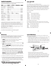
camera body. Position the Gear Sleeve teeth so they mesh with
the housing drive gear
((FFiigg.. JJ))
. When the port is installed it will
lock the Gear Sleeve in place After installing the port, rotate the
housings Zoom Control Knob to see that the Gear Sleeve is
properly rotating the lenses Zoom ring.
TOP OF HOUSING
Figure J
black housing
sleeve/
drive gear
mesh
gear sleeve
with
black housing
drive gear
11
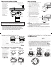
IInnssttaallll tthhee GGeeaarr SSlleeeevvee
After the Zoom Clamp is installed, lower the appropriate Gear
Sleeve over the Zoom Clamp aligning the Gear Sleeve ribs with the
grooves in the Zoom Clamps extended tabs as shown
((FFiigg..DD && EE))
.
Note that the ribs of the Gear Sleeve should slide freely in the
grooves of the Zoom Clamp. If the Gear Sleeve does not slide
freely, remove any rubber strips on the inside of the Zoom Clamp,
if no rubber strips are installed then try using the Zoom Clamp
and Gear Sleeve for Type 2 lenses in the #5509.28 package.
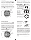
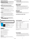
Lower the Gear Sleeve into the port opening of the housing so
the teeth on the Gear Sleeve mesh with the teeth on the housing
D
rive Gear
((FFiigg.. GG))..
W
hen the port is installed it will lock the
Gear Sleeve in place. After installing the port, rotate the housings
Zoom Control Knob to see that the Gear Sleeve is properly
rotating the lenses Zoom ring.
TOP OF HOUSING
Figure G
black housing
sleeve/
drive gear
mesh
gear sleeve
w
ith
black housing
d
rive gear
9
10
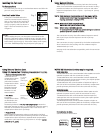
IInnssttaalllliinngg tthhee ZZoooomm CCllaammpp && GGeeaarr SSlleeeevvee OOnn TTyyppee 22 LLeennsseess
Due to the larger diameter of lens opening on Type 2 lenses, the
Zoom Clamp and Gear Sleeve need to be installed from the rear
(bayonet end) of the lens. Use the housings Lens Release Control
a
nd remove the camera lens from the camera body.
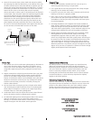
IInnssttaalllliinngg tthhee ZZoooomm CCllaammpp
The Zoom Clamp has springs so
it can be expanded to fit over the
Zoom ring of the lens as shown
in
((FFiigg.. II))
. Install the Zoom Clamp
with the extension tabs toward
the rear element of the lens. After
installing the Zoom Clamp, check
that when rotating the Zoom
Clamp it rotates the
Zoom ring on the
l
ens. If the Zoom
Clamp is not tight
enough to rotate
the Zoom ring on
the lens, remove
the Zoom Clamp
and install the rubber
strips (supplied) to the inside of
the Zoom Clamp as shown
((FFiigg.. HH))
.
Two thickness of rubber strips
are provided. Start by installing
the thinnest rubber strips, if the
Zoom Clamp still is not tight
enough use the thicker rubber
strips. Reinstall the Zoom Clamp.
c
lamp
Type 2 Installation: Figure 1
T
OP OF HOUSING
F
igure I
Type 2
lens
apply
r
ubber strips
to inside of
c
lamp
Figure H
z
oom
ring
align
z
oom clamp
e
xtension
grooved
t
ab with
gear sleeve
r
ibs
12
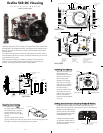
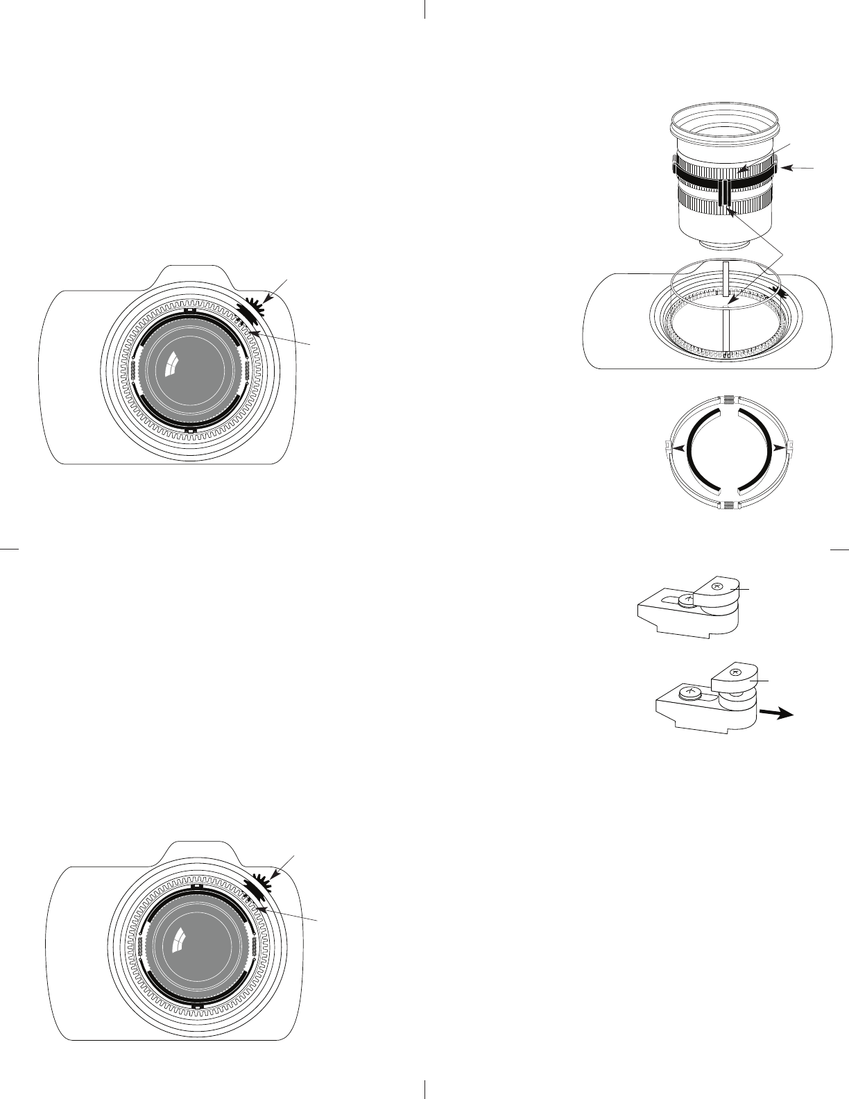
IInnssttaalllliinngg tthhee PPoorrtt
There are two port locks on
the front of the housing.
(See housing front) Each
port lock has a Release
Button, lift the release
button and slide each Port
Lock away from the port
opening. In the unlocked
position the Release Button
will remain in the up
position as shown.
To prepare the port for installation, remove the port o’ring and
lightly lubricate it. The port seal is a side-to-side seal and
requires the o’ring to be lightly lubricated for easy installation.
Put a small amount of lubricant on your fingers and draw the
o’ring through your fingers to lightly lubricate it. Do not stretch
the o’ring. Check that the lip of the port where the o’ring fits
and the sealing surface on the housing are clean. Place the port,
with o’ring into the housing’s port opening. Press down on the
port firmly and evenly until you feel the port slide into place.
Continue to push down on the port and push each port lock
forward until it clicks into place. It may help to slightly rotate
the port as you push in on the port lock. When the port lock
clicks into place the Release Button will drop down against the
port lock.
Check around the perimeter of the port seal to see that the
o’ring is properly sealed and not extruded.
Port Lock
Release
Button
Lift Release
Button to
Unlock
Pull Back to
Disengage
Port
Unlocked Position
Locked Position